
Audio Mixer with preamplifier
The mixer circuit described operates as a virtual earth mixing amplifier, characterized by its inverting configuration. This configuration is essential as it maintains the absolute polarity of the signal, which is particularly useful when integrating with tone control circuits that also employ inverting amplifiers. The gain of the mixer can be adjusted through the resistor values R115 and R215, with a standard configuration providing a gain slightly over two times. Setting these resistors to a value of 10k achieves a unity gain of -1, ensuring that the output signal is phase-inverted relative to the input.
The printed circuit board (PCB) dimensions are approximately 50 mm by 75 mm, making it compact and suitable for various applications. The design allows for flexibility, permitting users to customize the inputs based on their requirements by integrating additional circuits such as phono and microphone preamps. This adaptability is a significant advantage, as it opens up a wide range of potential applications limited only by the user's creativity.
The first amplification stage utilizes a buffer configuration, providing a gain of 2 (approximately 6 dB). The gain can be modified by changing the resistor values of R104 and R204; increasing the resistance results in lower gain, while decreasing it yields higher gain. However, caution is advised not to exceed a gain of four times (12 dB) to prevent DC offset issues. For optimal performance, a resistor value of 2.7k for R104/204 is recommended, yielding a gain of approximately 3.7 (11.4 dB), which is suitable for most applications.
The design does not incorporate potentiometers on the PCB to enhance flexibility, allowing users to select the most appropriate components for their specific setups without being constrained by predefined layouts. This approach facilitates easier construction and customization, accommodating various potentiometer types and arrangements.
The power supply requirements for the circuit are flexible, allowing for dual supplies ranging from +/-9V to +/-15V. This flexibility ensures compatibility with different power sources, making it suitable for portable applications or integration with existing power supply systems. It is important to adhere to the specified voltage range to maintain circuit integrity and performance.
The use of TL072 opamps in the design is standard, but the circuit can accommodate other industry-standard dual opamps, providing additional options for users based on availability and performance needs. This versatility further enhances the circuit's applicability across various electronic projects.The mixer is the common "virtual earth" mixing amplifier, and there is nothing special about it. Note that it is inverting, which complements the tone controls (also inverting) so the absolute signal polarity is maintained. As shown, the mixer also has a gain of a little over two times, and again this can easily be changed.
Making R115/215 10k sets the gain at -1 (i.e. unity, but inverted). Note that R117/217 are not mounted on the board, but mount directly on the output level control. The circuit is very simple, and the PCB is nice and small (approx 50 x 75 mm). The idea is that one PCB would be wired with all components (Figure 1 and Figure 2), while the others only use the section shown in Figure 1. You can select the inputs you need, and add the appropriate input circuits, such as phono preamps, mic preamps, etc.
Indeed, the range of uses is determined more by imagination than any "limitations" in the circuitry itself. The first stage (U1) is a buffer, but provides a gain of 2 (6dB) as shown. The gain is easily changed by changing the value of R104 (and R204 in the "B" Channel) - a higher value gives less gain, and vice versa.
I don't recommend that the gain be increased beyond about 4 times (12dB), or DC offset will become a problem. A value of 2k7 (2.7k) for R104/204 will give a stage gain of 3.7 (11.4dB) which should be more than enough.
A microphone preamp is a must if very low level signals are intended. If the ESP board is used, construction is very easy. It is small, but laid out very logically so it is easy to construct. No pots are mounted on the PCB - not because I like running wires (and I don't expect you do either) but because this gives you far greater flexibility for your version of the project. If I designed the board with the pots, then you would have to use the same type as I designed for, and the same spacings and layout.
This is very restricting - especially if you can't get (or don't want to use) the same type of pot. The power supply may be from +/-9V (for portable use), or +/-15V for use with the P05 power supply. Any dual supply may be used, so if you have one already, it may be used as long as the voltage is between +/-9V and +/-15V. Higher or lower voltages are not recommended. I have shown the circuit with TL072 opamps, but you may use anything you like (must be an industry dual opamp though).
🔗 External reference
Related Circuits
This is a simple circuit that features high-performance power amplifiers. The power amplifier is available as a PCB, along with a complete list of components. The described circuit utilizes high-performance power amplifiers, which are essential for applications requiring significant signal...
While I would have liked a 4 channel chip with about 20 Watt per channel, the local parts store didn't have any yet, so I opted for two TA8215AH stereo chips, selected by their low price in this particular...
This circuit is designed for an audio amplifier project to control the speaker output relay. Its primary function is to activate the relay that connects the speaker output to the amplifier after a delay of approximately 5 seconds following...
This preamplifier has a low output impedance, and is designed to drive long cables, allowing you to listen to a remote music source without having to buy expensive screened cables. The very low output impedance of around 16 ohms...
To commemorate the hundredth design posted on this website and to meet the requests of numerous correspondents desiring a more powerful amplifier than the 25W MosFet, a 60 - 90W high-quality power amplifier design is presented. The circuit topology...
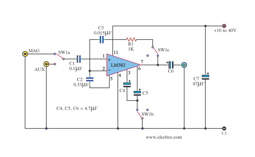
This is a simple preamplifier circuit. It can accept a general AUX sound signal as well as a signal from a microphone. The purpose of the circuit is to amplify the sound signal at the initial stage using an...
Warning: include(partials/cookie-banner.php): Failed to open stream: Permission denied in /var/www/html/nextgr/view-circuit.php on line 713
Warning: include(): Failed opening 'partials/cookie-banner.php' for inclusion (include_path='.:/usr/share/php') in /var/www/html/nextgr/view-circuit.php on line 713