
60 Watt Audio Power Amplifier
The 60 - 90W high-quality power amplifier circuit is designed to deliver exceptional audio performance while maintaining reliability and stability. The use of IRFP240 and IRFP9240 MosFet devices as output transistors ensures high efficiency and thermal robustness, making them suitable for demanding audio applications. These components are selected for their ability to handle high currents and voltages, which is essential for achieving the desired output power levels without distortion.
The circuit topology closely resembles that of the previously established 25W MosFet amplifier, allowing for a smoother transition for users familiar with the earlier design. The inclusion of high-voltage Motorola transistors in the signal amplification stages enhances the linearity and fidelity of the audio signal, contributing to a high-quality output.
The power supply design is critical for the amplifier's performance. A supply rail voltage of ±40V provides a stable operating environment, while the option to increase this to ±50V allows for greater output power without compromising performance. Careful consideration should be given to the capacitance values for C1 and C2; while 10,000 µF is recommended for stereo applications, users should ensure that the capacitance is sufficient to maintain voltage stability during high-demand audio passages.
Grounding is a vital aspect of the design, as improper grounding can lead to unwanted noise and interference. The specific grounding scheme outlined ensures that all components share a common ground reference, minimizing the risk of ground loops and hum. This meticulous attention to grounding practices is essential for achieving a clean and clear audio signal.
In summary, this high-quality power amplifier design not only meets the demand for increased power but also adheres to best practices in circuit design and grounding, ensuring a superior audio experience.To celebrate the hundredth design posted to this website, and to fulfil the requests of many correspondents wanting an amplifier more powerful than the 25W MosFet, a 60 - 90W High Quality power amplifier design is presented here. Circuit topology is about the same of the above mentioned amplifier, but the extremely rugged IRFP240 and IRFP9240 MosF
et devices are used as the output pair, and well renowned high voltage Motorola`s transistors are employed in the preceding stages. The supply rails voltage was kept prudentially at the rather low value of and - 40V. For those wishing to experiment, the supply rails voltage could be raised to and - 50V maximum, allowing the amplifier to approach the 100W into 8 Ohm target: enjoy!
A matching, discrete components, Modular Preamplifier design is available here: Modular Audio Preamplifier. In the original circuit, a three-diode string was wired in series to R10. Two of these diodes are now replaced by a red LED in order to achieve improved quiescent current stability over a larger temperature range.
Thanks to David Edwards of LedeAudio for this suggestion. The value suggested for C1 and C2 in the Power Supply Parts List is the minimum required for a mono amplifier. For optimum performance and in stereo configurations, this value should be increased: 10000 F is a good compromise.
A correct grounding is very important to eliminate hum and ground loops. Connect to the same point the ground sides of R1, R3, C2, C3 and C4 and the ground input wire. Connect R7 and C7 to C11 to output ground. Then connect separately the input and output grounds to the power supply ground. 🔗 External reference
Related Circuits
Low-noise preamplifier circuit. This circuit demonstrates a typical low-noise preamplifier design, which can be utilized to amplify signals from sources such as magnetic heads and microphones within audio applications. The input signal is coupled through a capacitor and subsequently...
A simple audio compressor is designed using the SSM2165 integrated circuit (IC). There is limited explanation available regarding the schematic of this compressor circuit; however, special attention should be given to the capacitor used. The audio compressor circuit utilizing the...
A radio camera on a model railway is designed to transmit continuously while the train is in motion and to continue transmitting for a few minutes after the train stops. If the train starts moving again after a relatively...
A simple oscillator that can be utilized for code practice. To achieve adequate inductance for generating an audio frequency, an iron core transformer, similar to those employed in audio transformer-coupled amplifiers, is connected as illustrated. The circuit comprises a basic...
In addition to its primary function as a headphone amplifier, the circuit is suitable for various applications requiring a wide bandwidth low power amplifier. It is constructed using an operational amplifier (op-amp), with its output current enhanced by a...
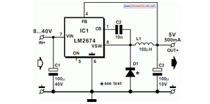
National Semiconductor has been producing and designing integrated circuits (ICs) for use in switch-mode power supplies for many years. The application of these devices is standard. National Semiconductor has established a significant presence in the design and manufacturing of integrated...