
Simple Preamplifier by LM382

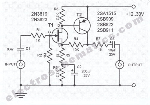
The described preamplifier circuit is designed to enhance audio signals from various sources, including AUX inputs and microphones. The circuit typically employs an operational amplifier, which is a high-gain voltage amplifier with differential inputs and a single-ended output.
In the schematic, the op-amp is configured in a non-inverting mode, which allows for a significant increase in the input signal's amplitude while maintaining the original phase. The input stage may include capacitors to block any DC offset from the audio signals, ensuring that only the AC components of the audio are amplified. Resistors are also used in the feedback loop to set the gain of the amplifier, which can be adjusted based on the specific requirements of the application.
Power supply considerations are crucial for the op-amp's operation; a dual power supply (positive and negative voltage rails) is often used to accommodate the full range of audio signals. Bypass capacitors may be included to filter out any noise from the power supply, ensuring a clean and stable operation of the op-amp.
The output of the preamplifier can be connected to further stages of audio processing, such as tone controls or additional amplification stages, making this circuit an essential component in audio signal processing applications. Proper grounding and layout techniques are important in the design to minimize noise and interference, which can adversely affect audio quality.This be simple Preamp circuit. It can take sound general signal AUX and a signal from Microphone. For enlarge sound signal at the beginning. By use op-amp IC.. 🔗 External reference
Related Circuits
A sawtooth wave generator circuit using a 555 IC is presented in the article below. The frequency equation is provided with the supply voltage Vcc. The sawtooth wave generator circuit utilizing a 555 timer integrated circuit (IC) is a fundamental...
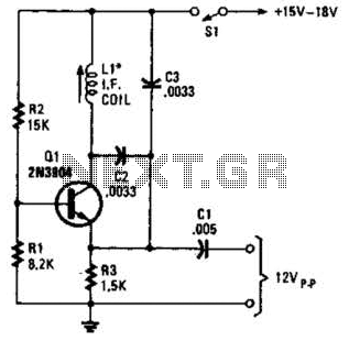
A simple oscillator for intermediate frequency (IF) alignment at 455 kHz can be useful in field testing or in scenarios where a standard signal generator is available. The inductor (L1) should resonate at the desired output frequency with the...
This microphone preamplifier utilizes the low-noise integrated circuit uA739. The circuit serves as an example of an effective preamplifier design for dynamic microphones. The integrated circuit contains two identical preamplifier circuits, with the second preamp functioning in the same...
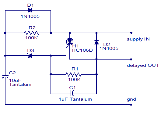
The circuit diagram presented is of a straightforward DC power delay circuit utilizing a silicon-controlled rectifier (SCR). This circuit is quite useful and can be applied in various scenarios. The operation of this circuit is uncomplicated. Upon the application...
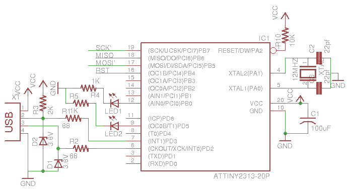
This is a low-cost AVR programmer using the ATtiny2313. The schematic diagram is provided below. First, set up the circuit as shown. One important consideration is to configure the fuse bits using the command: avrdude -c usbasp -p t2313...
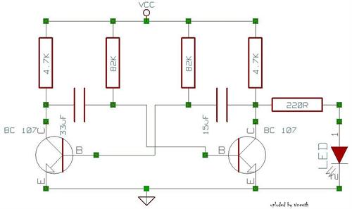
An astable multivibrator is a switching circuit that alternates its output on and off for a designated time period. This device, also known as a free-running oscillator circuit, is primarily utilized to generate square waves over a specified duration....