
Audio Notch Filter For Shortwave Receivers Circuit
A notch filter, also known as a band-stop filter, is designed to selectively attenuate a narrow band of frequencies while allowing all other frequencies to pass with minimal loss. In the context of receiver applications, its primary role is to eliminate unwanted signals or noise that can interfere with the desired audio or data transmission.
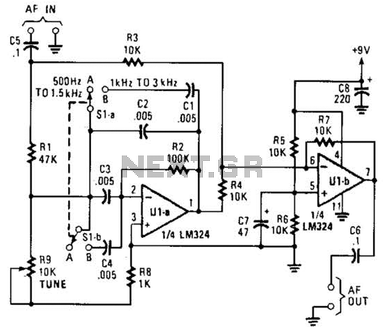
The design of a notch filter typically involves the use of passive components such as resistors, capacitors, and inductors, or it can be implemented using active components like operational amplifiers for improved performance. The center frequency of the notch, where the attenuation occurs, is determined by the values of the reactive components in the circuit.
For practical implementation, the notch filter can be configured in various ways, including a parallel LC circuit, where an inductor (L) and capacitor (C) are connected in parallel to ground. The resonant frequency, at which the circuit exhibits maximum attenuation, is given by the formula:
f_0 = 1 / (2π√(LC))
Where f_0 is the resonant frequency in hertz, L is the inductance in henries, and C is the capacitance in farads.
In applications where heterodynes and whistles are prevalent, such as in radio communications or audio processing, the notch filter effectively reduces these unwanted frequencies, enhancing the overall clarity and quality of the received signal. By adjusting the component values, the filter can be fine-tuned to target specific frequencies of interest, making it a versatile tool in electronic design.
The notch filter can be implemented in both analog and digital domains, with digital signal processing (DSP) techniques allowing for more complex filtering capabilities and adaptability to varying signal conditions. This flexibility makes the notch filter a vital component in modern communication systems, ensuring that the integrity of the desired signal is maintained while minimizing the impact of disruptive noise. The notch filter can be added to just about any receiver to attenuate a single frequency by more than 30 dB. This filter should be handy for reducing heterodynes and whistles. 🔗 External reference
Related Circuits
This automatic light dimmer circuit enables the gradual control of a lighting system, allowing it to turn on or off slowly. The operation of the circuit is as follows: when switch S1 is closed, capacitor C1 charges slowly. Once...
Various values of D3 can be utilized to achieve different output voltages ranging from approximately 0.6V to around 30V. It is important to note that at elevated voltages, the circuit's performance may diminish, potentially resulting in lower current output....

The required output from the inverter is 220/230V at 60Hz, with an output power of 1000VA. The first circuit represents a basic commercial UPS design, providing a constant regulated 5V output and an unregulated 12V supply. Upon failure of...
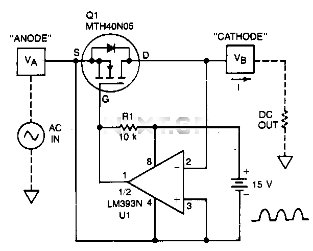
A TMOS power FET, Q1, and an LM393 comparator provide a high-efficiency rectifier circuit. When voltage V1 exceeds V2, the output of U1 becomes high, and Q1 conducts. Conversely, when V2 exceeds V1, the comparator output becomes low, and...
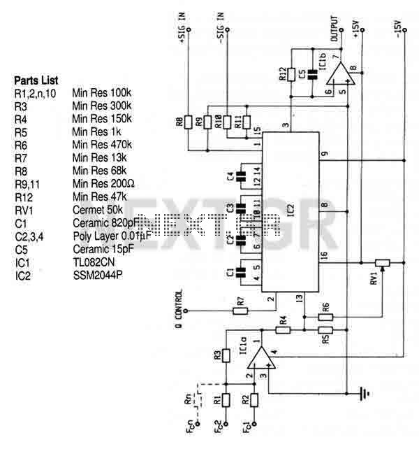
This circuit utilizes the SSM2044 integrated circuit (IC), which is a four-pole voltage-controlled filter specifically designed for electronic music applications. The on-chip voltage control of resonance facilitates straightforward interfacing with programmers and controllers. The IC is characterized by an...
The circuit below is a simple dimmer circuit. A network consisting of R1, R2, VR1, C2, C3, and Q1 controls the triggering angle of the triac by adjusting the variable resistor VR1. The described dimmer circuit employs a TRIAC (Q1)...