
Automatic lamp dimmer circuit
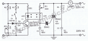
The automatic light dimmer circuit utilizes several key components to achieve its functionality. The primary components include a switch (S1), a capacitor (C1), a transistor (T1), a light-dependent resistor (LDR), a silicon-controlled rectifier (SCR), a diode (D1), and a potentiometer (P2).
When the circuit is powered, the closing of switch S1 initiates the charging process of capacitor C1. The slow charging is crucial as it determines the time delay before the LED lights up. The voltage threshold of 0.6 volts across C1 is significant as it activates transistor T1. This transistor acts as a switch that controls the current flow to the LED based on the voltage level of the capacitor.
The interaction between the LED and the LDR is essential for the dimming effect. As the LED illuminates, the resistance of the LDR decreases, which allows the SCR to conduct sooner than it would otherwise, thereby enhancing the gradual illumination of the lighting system.
The gradual dimming effect when switch S1 is opened is achieved through the slow discharge of the capacitor C1. This characteristic ensures that the LED does not turn off abruptly, providing a more aesthetically pleasing transition from bright to dark.
The adjustment of potentiometer P2 plays a critical role in setting the operational parameters of the circuit. By ensuring that the anode voltage of diode D1 is approximately 0.7 volts, the circuit is optimized for performance, allowing the capacitor to maintain a standby voltage of around 0.5 volts when the lights are off.
Overall, this automatic light dimmer circuit is a practical solution for applications where gradual lighting control is desired, enhancing both functionality and user experience.This automatic light dimmer circuit makes it possible to control a lighting system so that it turns on or off slowly. The circuit works this way: when switch S1 is closed, the capacitor C1 is slowly charged. Once the voltage at C1 reaches 0. 6, transistor T1 begins to conduct and the LED also begins to light. If the capacitor voltage increases furt her, then transistor T1 conducts more current and in return the LED lights brighter. If the LED lights up, the LDR resistance decreases causing the SCR to conduct periodically earlier. This tehnique causes the lighting system to turn on slowly. On the other hand if switch S1 is turned off, meaning the switch is opened, the LED does not immediately turn off since the capacitor voltage at the base of T1 discharges slowly. The LED slowly dims until finally turns off. This causes the lighting dim out before it finally turns off. Potentiometer P2 must be set so that the anode voltage of D1 is about 0. 7 volts. If this is done, the capacitor voltage will be around 0. 5 volts during standby, meaning lights off. We aim to transmit more information by carrying articles. Please send us an E-mail to wanghuali@hqew. net within 15 days if we are involved in the problems of article content, copyright or other problems.
We will delete it soon. 🔗 External reference
Related Circuits
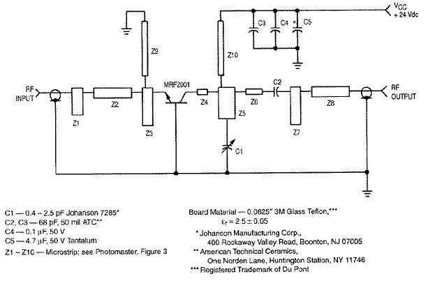
RF amplifier circuit diagram, delivering 1W for 2.3GHz, built based on MRF2001. This RF amplifier provides approximately 1 Watt power output with a minimum gain of 8 dB at a 24V voltage supply. The frequency can be tuned from...
Are you unfamiliar with the basics of electronics? An online store has recently opened, offering four excellent books on basic electronics for sale. Reviews of these books are available, and purchases can be made as desired. These books are...
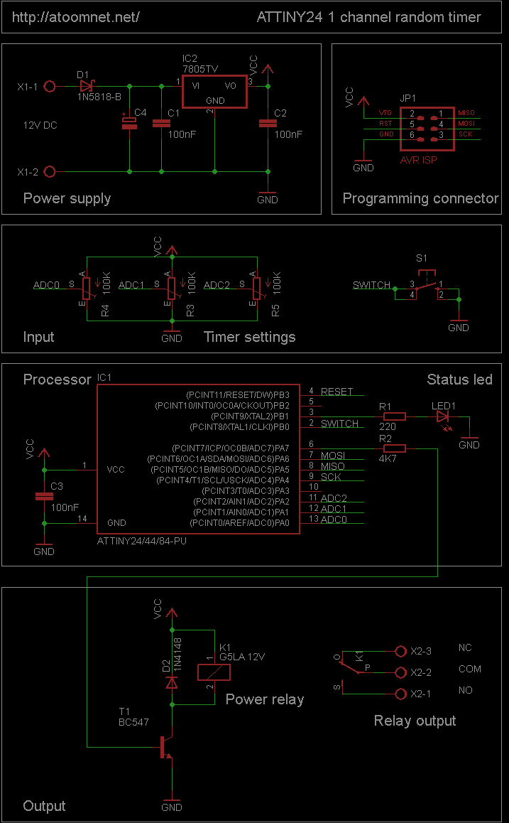
This random timer circuit is based on an Atmel ATTINY24 AVR driving one power relay. It can be used to switch on and off other circuits randomly. For instance, in a model railroad setup, this circuit can activate and...
Nokia BL-4C and BL-5C are 3.7V, 700-1000mAh (various) lithium-ion batteries that have three terminals. These terminals include a positive terminal, a ground, and a BSI (Battery Status Indicator) terminal, which presents a fixed resistance value that needs to be...
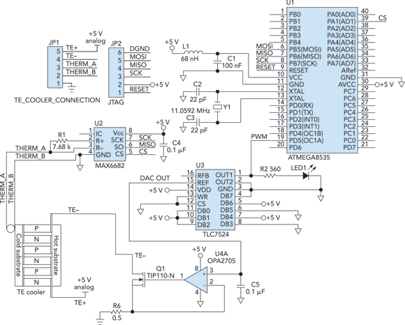
Cooling an instrument or device can enhance the signal-to-noise ratio (SNR) and extend the product's lifespan. For instance, the dark-and-noise signal of an infrared detector's output at room temperature can be significantly reduced when cooled. A custom cooling device...
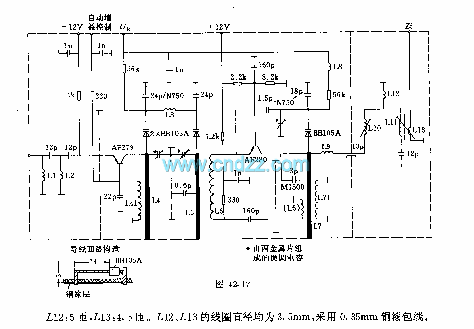
The circuit features an adjustable prestage utilizing the AF279 transistor, while the natural oscillation mixer stage employs the AF280 transistor. The power circuit is mounted on a board with copper coating. The main coil specifications are as follows: L1,...