
Light Dimmer Circuit
The described dimmer circuit employs a TRIAC (Q1) to regulate the power delivered to a load, such as a lamp or motor. The primary components include resistors R1 and R2, a variable resistor (potentiometer) VR1, and capacitors C2 and C3, which work together to establish the phase control necessary for dimming.
The operation begins with the charging of capacitor C2 through the resistors R1 and R2. The time constant for this charging process is influenced by the values of these resistors and the capacitance of C2. As VR1 is adjusted, it alters the resistance in the circuit, which in turn changes the charging time of C2. The voltage across C2 rises until it reaches a certain threshold, at which point it triggers the TRIAC.
The TRIAC conducts, allowing current to flow to the load. The point at which the TRIAC is triggered determines the phase angle of the AC waveform that is allowed to pass through to the load, effectively controlling the power delivered. This phase control is what enables the dimming function, as a later trigger point results in less power being delivered to the load.
Capacitor C3 may be included to filter out noise and stabilize the voltage levels in the circuit, ensuring reliable operation. Proper selection of the component values is crucial for achieving the desired dimming range and response time. Additionally, the circuit may benefit from protective components, such as a fuse or circuit breaker, to prevent damage from overcurrent conditions.
Overall, this simple dimmer circuit exemplifies an effective method for controlling AC power and can be applied in various lighting and motor control applications.The circuit below is a simple dimmer circuit. Network of R1, R2, VR1, C2, C3 and Q1 controls the triggering angle of the triac by varying the variable resistor VR1.. 🔗 External reference
Related Circuits
This is a simple transistor tester circuit that can be utilized to test both NPN and PNP transistors. The voltage source consists of a 6V power supply, which is derived from a step-down transformer that converts 230V AC to...
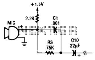
This circuit is suitable for using an electret microphone for various applications. A 1.5-V battery is utilized. CI and R3 provide treble boost and bass cut; they can be eliminated if desired. The described circuit employs an electret microphone, which...
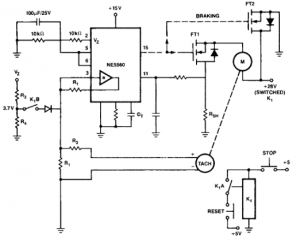
This circuit is useful for creating a constant speed motor control, ensuring that the motor speed remains constant despite variations in load and electrical voltage. The circuit for a constant speed motor control typically employs feedback mechanisms to maintain a...
This device utilizes the MC145026/MC145027 encoding and decoding circuit along with the TDA1808/TDA1809 RF transmitter/receiver module. It can be operated flexibly within a range of 10 to 120 meters, allowing users to maintain the original external appearance and internal...
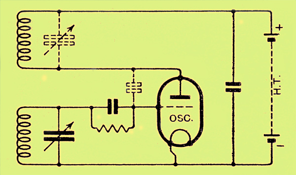
The congestion of the ether is increasing, prompting ongoing efforts to extend communication channels to higher frequencies. Wavelengths as short as 12 meters are now common, but operating below this presents significant challenges. At approximately one meter, the oscillation...
For optimal lifespan, it is recommended to operate LEDs at 20-25 milliamps (mA). However, in certain LED flashlight conversions, including many commercial LED flashlights, the LEDs are often driven at 50-60 mA, which is twice the rated current. Testing...