
Audio Signal Strength Detector/Converter
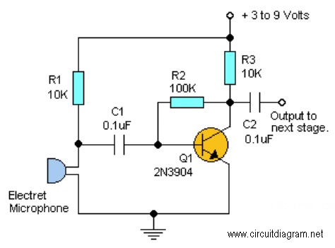
The audio input module typically consists of several key components that work together to convert an AC audio signal into a DC voltage level. At the core of this module is an operational amplifier (op-amp), which is configured in a non-inverting mode to amplify the incoming audio signal. The op-amp's gain can be adjusted using external resistors, allowing for customization based on the desired output level.
The input stage may include a coupling capacitor, which serves to block any DC offset from the audio signal while allowing the AC component to pass through. This ensures that only the varying part of the signal is processed by the op-amp. The output of the op-amp is then fed into a rectifier circuit, which converts the AC signal into a pulsating DC voltage. A smoothing capacitor is often employed after the rectifier to filter out the ripples in the DC output, providing a more stable voltage level that accurately reflects the amplitude of the original audio signal.
To further enhance performance, a voltage divider may be implemented at the output stage to scale the DC voltage to a desired range, making it suitable for interfacing with other electronic components or systems. Additionally, protection diodes can be included to safeguard the circuit against voltage spikes or reverse polarity, ensuring longevity and reliability in various operating conditions.
The schematic diagram visually represents these components and their interconnections, providing a clear understanding of the audio input module's functionality and operation.Below is the schematic diagram of an audio input module. We can produce a DC output voltage that is proportional to the input signal amplitude (the signal.. 🔗 External reference
Related Circuits
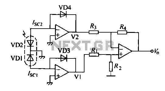
The operation of a semiconductor color sensor can be summarized as follows. The figure illustrates the spectral response curve of two photodiodes that intersect at a specific wavelength. When light of this wavelength is incident on the photodiodes, the...
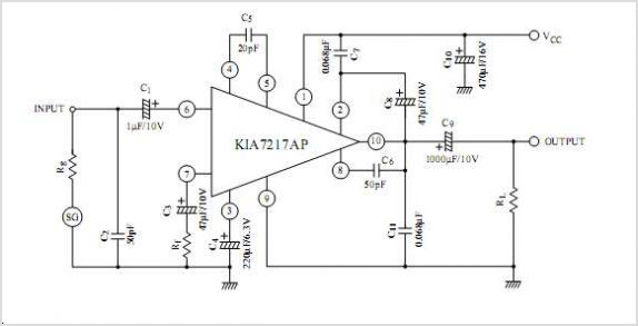
The UTC L2572 is a wideband PLL FM demodulator designed primarily for use in satellite tuners. It incorporates all essential components, except for the loop feedback elements, to create a complete PLL system capable of operating at frequencies up...
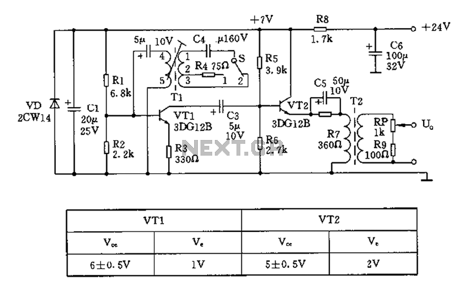
The 450/800Hz oscillation circuit depicted in the figure utilizes transformer coupling. The frequency conversion is achieved by varying the inductance through a variable filter tap (T1). When the switch control signal (S) is set to position 1, the oscillator...
This project requires expensive hardware, including a microphone and amplifier, along with sophisticated audio analysis on the microcontroller. Even a complete microphone with an amplifier circuit does not yield the desired results, as noted in the product comments. The...
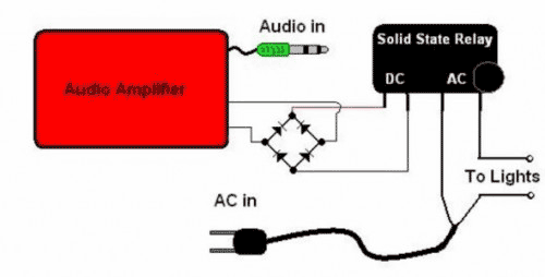
The basic Idea was to have Christmas lights flash with the music. In my design I use an ordinary amplified computer speaker, a diode bridge, and a ‘CRYDOM’ SSR (Solid State Relay). In order to increase the time that...
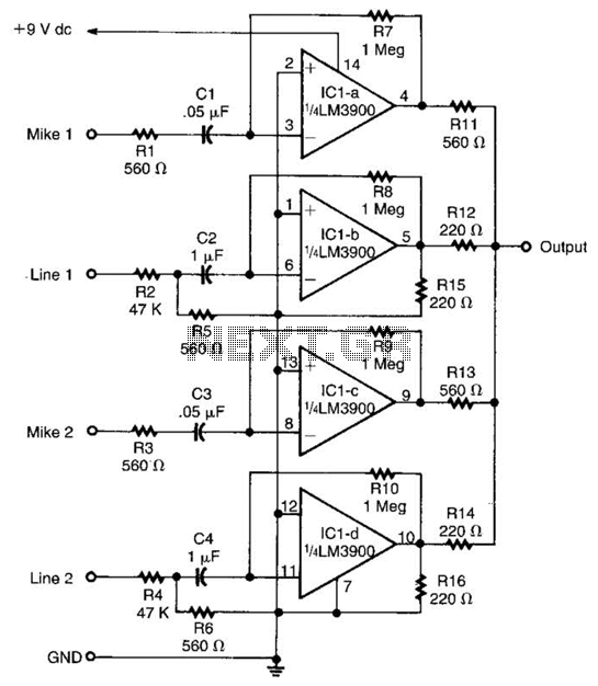
Designed around an LM3900 quad op amp, this mixer combines two line inputs and two microphone inputs, summing them at the output terminal. Resistors R7 through R10 can be adjusted to vary the gain, approximately +23 dB. The mixer circuit...