
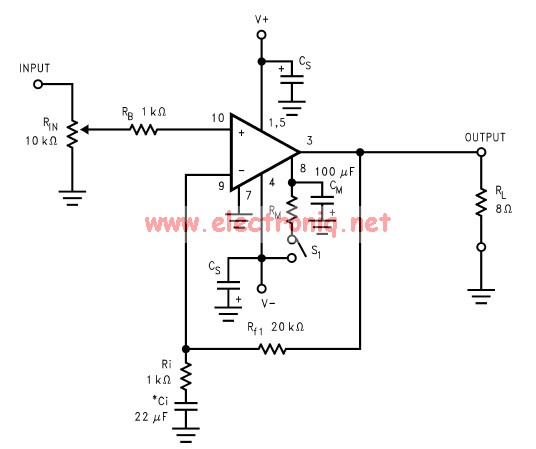
Audio-To-Adc Interface Circuit

The circuit consists of two operational amplifiers (op-amps) from the 741 series, which are configured to provide adjustable gain and offset for the input signal. The first op-amp is configured as a non-inverting amplifier, allowing for the amplification of the input voltage while maintaining its phase. The gain of this amplifier can be adjusted using a feedback resistor network, which typically includes a variable resistor (potentiometer) to facilitate fine-tuning.
The output from the first op-amp is then fed into the second op-amp, which serves as a summing amplifier. This configuration allows for the addition of a DC offset to the amplified signal, enabling the adjustment of the output voltage range to match the requirements of the analog/digital converter. The offset can be introduced by connecting a reference voltage to one of the input terminals of the second op-amp, again utilizing a potentiometer for precise control.
It is important to note that while the 741 op-amps are suitable for many applications, other op-amps with similar specifications may be used in this circuit. However, substituting different op-amps may necessitate recalibrating the gain and offset settings to ensure optimal performance. Proper attention should be given to the power supply requirements and frequency response characteristics of the chosen op-amps to maintain the integrity of the signal processing.
Overall, this driver circuit provides a flexible solution for interfacing analog signals with digital converters, facilitating a range of applications in signal conditioning and data acquisition systems. This simple general-purpose driver for an analog/digital converter uses two 741 IC devices with adjustable gain and offset, Other op amps might be substituted, but some circuit adjustments might be needed.
Related Circuits

The adjustable power supply can be reconfigured by changing the value of V2 and enhancing other components as needed. The output voltage is calculated using the formula Vnm = 1.25 (1 + R2/R^). Additionally, R2 can be modified as...
I designed a simple sinewave generator based on a Analog Devices AD9832 chip. It will generate a sinewave from 0.005 to 12 MHz in 0.005 Hz steps. That's pretty good, and definitely good enough for me! But while waiting...
The LM3886 amplifier electronic circuit project is designed to deliver 68W of continuous average power into a 4-ohm load and 38W into an 8-ohm load with a total harmonic distortion plus noise (THD+N) of 0.1% across the frequency range...
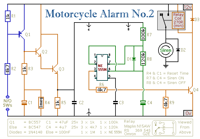
This circuit provides an intermittent siren output with an automatic reset function. It can be manually activated using a key switch or a concealed switch, and it can also be configured to engage automatically when the ignition is turned...
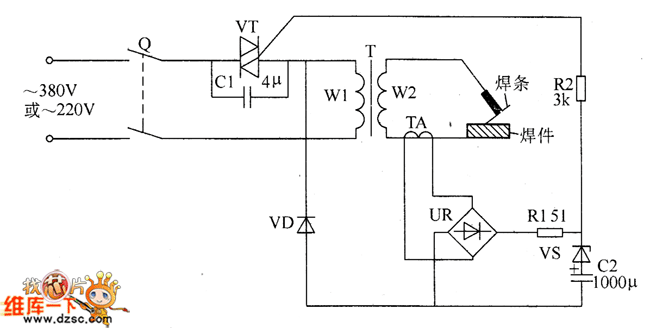
The welder no-load power saver circuit consists of a current detection control circuit and a power saving control circuit, as illustrated in the accompanying chart. The current detection control circuit includes a current transformer (TA), a bridge rectifier (UR),...
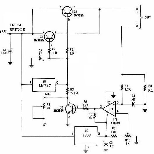
This universal battery charger utilizes the LM317 voltage regulator and features an adjustable output voltage along with a constant-current charging circuit, making it suitable for charging most NiCad batteries and various other battery types. The LM317 universal battery charger...