
Configurable Power Supply Circuit

The adjustable power supply circuit is designed to provide a variable output voltage based on the configuration of specific components. The core of this circuit typically employs a voltage reference and an operational amplifier (op-amp) in a feedback arrangement. The formula for the output voltage, Vnm = 1.25 (1 + R2/R^), indicates that the output voltage can be adjusted by varying the resistor R2, while R^ represents a fixed resistor in the circuit.
The voltage reference, often a precision device, ensures that the output remains stable despite variations in load current or input voltage. The op-amp amplifies the difference between the reference voltage and the feedback voltage derived from the output, thus maintaining the desired output level.
To enhance the performance of the adjustable power supply, other components may need to be beefed up. This can include capacitors for filtering, which reduce ripple voltage and improve transient response, as well as inductors or additional resistors that may be used to stabilize the output or adjust the response time of the circuit.
In practical applications, the ability to adjust R2 allows for a wide range of output voltages, making the power supply versatile for various electronic projects. Proper selection of R2 is crucial, as it directly influences the output voltage range and the stability of the supply. Additionally, ensuring that all components are rated for the intended load current and voltage is essential for reliable operation.
Overall, this adjustable power supply circuit is a fundamental design that can be tailored for specific requirements by modifying key components, thus providing flexibility for different electronic applications. The adjustable supply can easily be reconfigured by altering the value of V2 and beefing up some other components, as is necessary. The output voltage is given by Vnm = 1.25 (1 + R2!R^). R2 can be changed, as is necessary. 🔗 External reference
Related Circuits

Intercom walkie-talkies represent an advanced application of crystal oscillators for voice transmission. Utilizing a crystal-locked oscillator for voice transmission is complex due to the oscillator's fixed frequency, which is challenging to modulate. The primary method for achieving this involves...
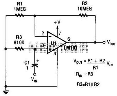
A general-purpose noninverting AC amplifier for audio and other low-frequency applications is presented. Design equations are included in the figure. Almost any general-purpose operational amplifier can be utilized for U1. The circuit configuration features a noninverting amplifier topology, which is widely...
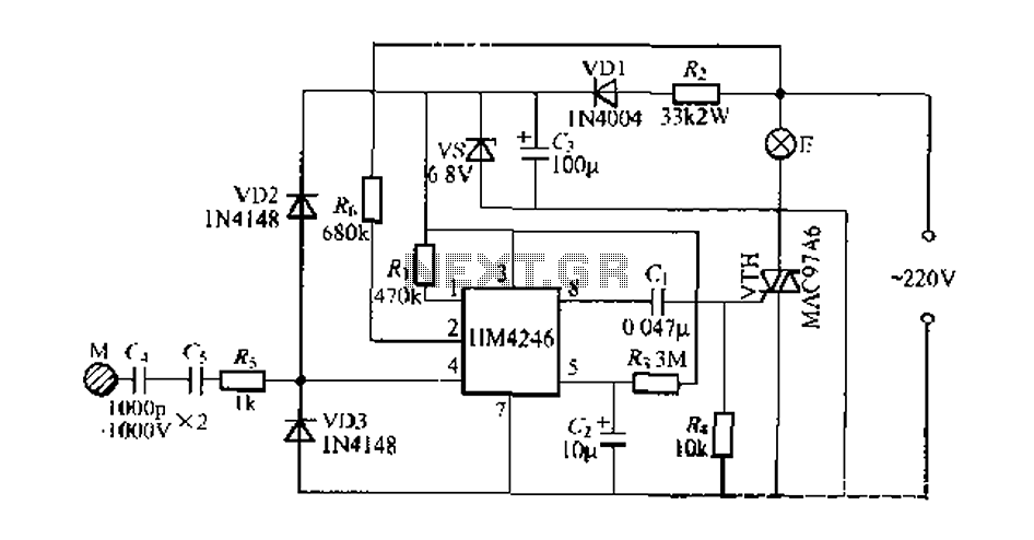
Development and production of a specialized touch dimmer integrated circuit. This circuit features four lighting functions: dark, medium, light, and a touch-sensitive trigger on all four sides. It has low harmonic radiation emission, high touch sensitivity, and stability. It...
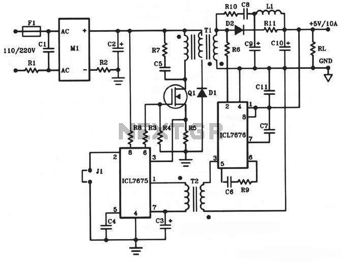
The following diagram illustrates a 50W offline switching power supply circuit design. This circuit is powered by a MOSFET, specifically the BUZ80A/IXTP4N8 for a 220V AC voltage input and the GE IRF823 for a 110V AC voltage input. The...

Conducting pipe rechargeable long delay control circuit. An adjustment potentiometer RP can delay up to several tens of seconds. The conducting pipe rechargeable long delay control circuit is designed to manage the timing of electrical signals, allowing for a delay...
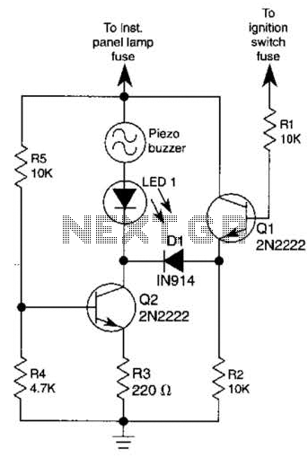
The base of Q1 is connected to the car's ignition circuit; the easiest point to make that connection is at the ignition switch fuse in the car's fuse panel. Also, one side of the piezoelectric buzzer is connected to...