
audio tone control 2 transistor circuit
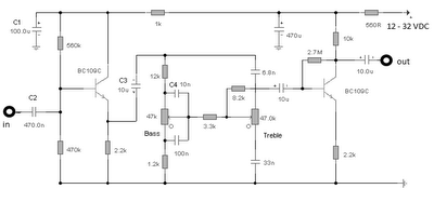
The circuit utilizes the BC109C transistor as a buffer stage, which is essential for maintaining high input impedance while minimizing loading effects on preceding stages. With an input impedance of approximately 250k, this transistor ensures that the signal source is not significantly affected by the circuit's characteristics, allowing for a faithful reproduction of the input signal. The voltage gain of slightly less than unity ensures that the output signal remains closely aligned with the input, preserving the integrity of the audio signal.
The Baxendall tone control circuit is a well-known passive equalization design that allows for the adjustment of audio frequencies without introducing significant distortion. In this configuration, all audio frequencies are attenuated, and the specific response characteristics can be manipulated by adjusting the positions of the tone control potentiometers and the reactance values of the capacitors used in the circuit. The interaction between the control settings and the capacitors determines the overall tonal balance, enabling the user to tailor the audio output according to their preferences.
The final transistor stage is designed to provide a modest gain of approximately 3 times, which is sufficient to drive subsequent audio amplification stages effectively. The output is optimized for connection to amplifiers with input impedances between 10k and 250k, ensuring compatibility with a wide range of audio equipment. The use of linear type potentiometers for the tone controls allows for smooth and precise adjustments, making it easier for users to achieve their desired sound profile. This combination of design elements results in a versatile and effective audio processing circuit suitable for various applications in audio engineering.The first BC109C transistor is acting as a buffer. It provides the circuit with a high input impedance, around 250k has a voltage gain of slightly less than unity. As the Baxendall tone control circuit is a passive design, all audio frequencies are attenuated. The position of the controls and reactance of the capacitors alters the audio response. The last transistor provides a slight boost of about 3x. The output is designed to feed an amplifier with input impedance of 10k to 250k. Both tone controls should be linear type Potentiometers. 🔗 External reference
Related Circuits
This document explains how to connect lights so that they flash when the phone rings. This setup is particularly beneficial in noisy environments, such as workshops, where it is challenging to hear the phone ringing. The ring detection component...
The following circuit illustrates an audio amplifier circuit diagram with a power output of 25 watts. Features include its widespread use in nearly all mass-market stereo receivers produced, providing enhanced sound quality. This audio amplifier circuit is designed to deliver...
The objective is to transmit additional information by distributing articles. Please contact us via email at [email protected] within 15 days if there are issues related to article content, copyright, or other concerns. We will promptly remove the articles if...
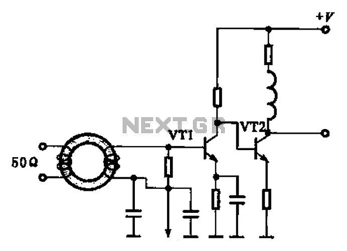
A broadband high-frequency amplifying circuit is primarily composed of a high-frequency matching transformer and an amplifying transistor. This circuit is designed to handle large high-frequency signals. The input of the amplifier circuit utilizes a matching transformer to ensure that...
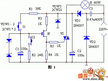
The keyer dimmer table lamp utilizes two touch buttons to adjust the light intensity. When one button is touched, the light dims from a strong brightness, while the other button increases the brightness from a dim state. The working...
A zero-crossing detector converts an input sine wave (Vin) into a square wave, which, when high, charges an op-amp integrator. A reference-input square wave subsequently discharges the integrator. The output voltage of the integrator at the end of this...