
Audio Amplifier 25 Watt
This audio amplifier circuit is designed to deliver a power output of 25 watts, making it suitable for various applications, including home audio systems, portable speakers, and other audio devices. The circuit typically employs a combination of transistors, resistors, capacitors, and possibly an operational amplifier to achieve the desired amplification.
The input stage of the amplifier often consists of a differential amplifier configuration, which helps in improving the signal-to-noise ratio and reduces distortion. The transistors used in the output stage are usually configured in a push-pull arrangement, allowing for efficient amplification of both the positive and negative halves of the audio signal. This configuration enhances the overall performance by minimizing crossover distortion.
Power supply considerations are crucial for achieving optimal performance in audio amplifiers. A regulated power supply is recommended to ensure stable voltage levels, thus preventing fluctuations that could affect sound quality. Additionally, bypass capacitors may be included to filter out high-frequency noise, further improving the amplifier's performance.
Heat dissipation is another important aspect to consider, as amplifiers can generate significant heat during operation. Adequate heat sinks or cooling mechanisms should be implemented to maintain the transistors within safe operating temperatures, ensuring reliability and longevity of the circuit.
Overall, this 25-watt audio amplifier circuit is a versatile design that can be adapted for various audio applications, providing robust performance and high-quality sound reproduction in consumer audio products.The following circuit shows about Audio Amplifier 25 Watt Circuit Diagram. Features: used in practically every mass market stereo receiver manufactured, better .. 🔗 External reference
Related Circuits
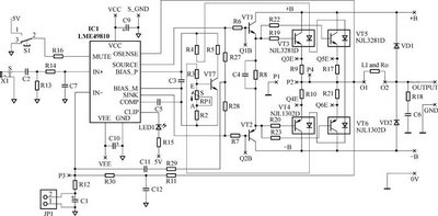
The following circuit illustrates the LME49810 integrated circuit used in a power amplifier circuit diagram. Features include improved drive capability for 4-ohm speaker impedance. The LME49810 is a high-performance audio power amplifier IC designed to deliver high output power with...
The circuit utilizes two 2N3819 FETs arranged in a cascode configuration. The lower FET functions in common source mode, while the upper FET operates in common gate mode, achieving full high-frequency gain. The lower FET is tunable, enabling peak...
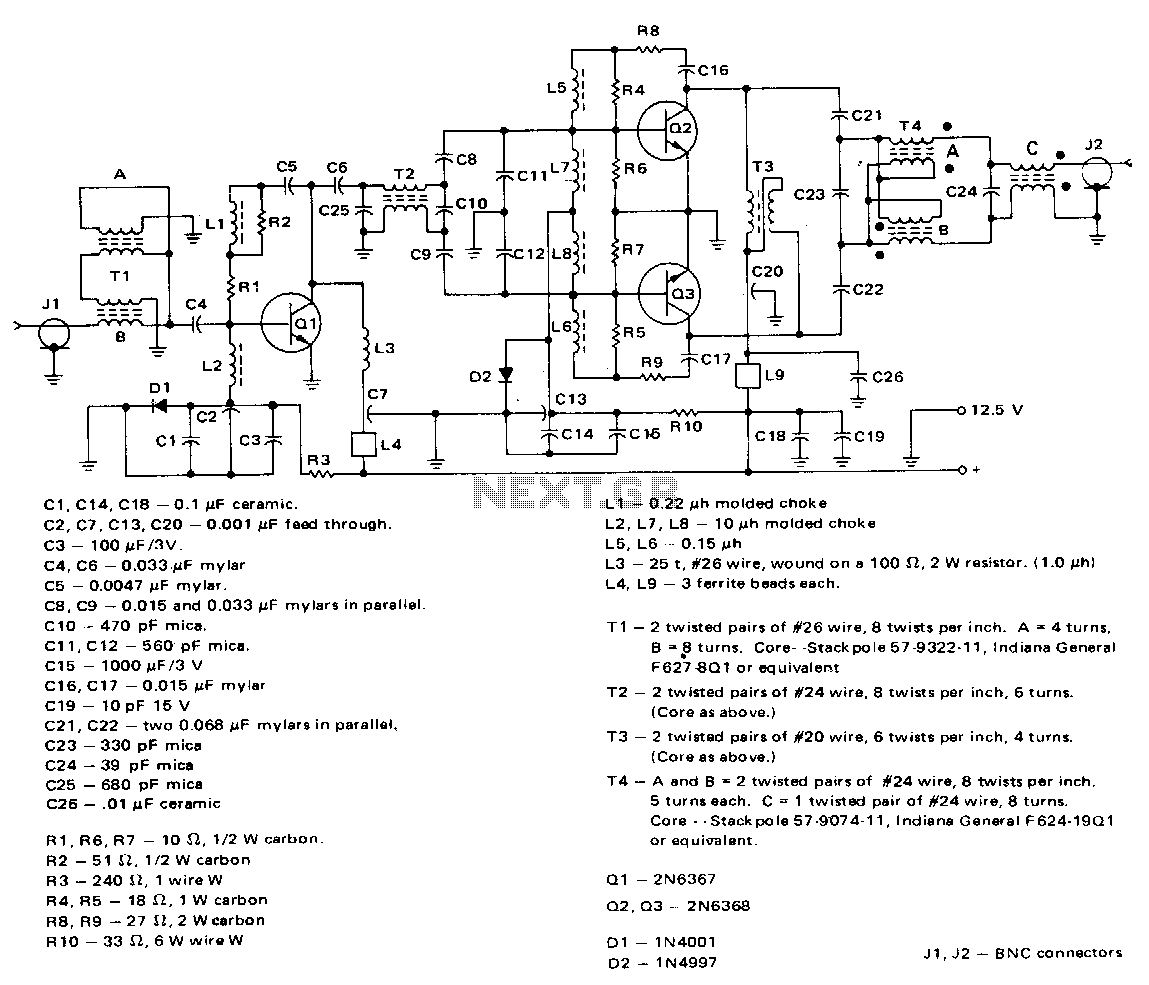
This amplifier employs a 2N6367 transistor as a driver along with a pair of 2N6368 transistors. The 2N6367 is rated for a maximum output of 9 W (PEP) and is required to deliver 5 W (PEP) at 30 MHz,...
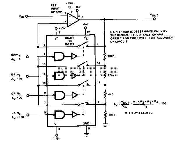
The circuit utilizes the DG212 to control gain through the use of resistors. To calculate the various gain levels, switch SW4 must be closed. Gain error is influenced solely by the tolerance of the resistors, the offset of the...
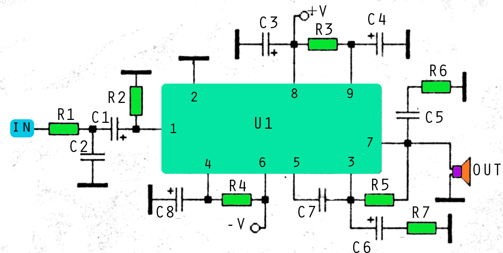
This amplifier circuit utilizes three voltage levels: positive, negative, and ground, with a maximum voltage of approximately 55V DC. The circuit can accommodate several integrated circuits (ICs), including STK 030, 058, 075, 077, 078, 080, 082, 083, 084, and...
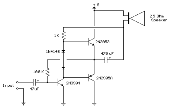
This circuit is similar to the previous one but employs positive feedback to enhance the amplitude delivered to the speaker. It was derived from a small 5-transistor radio utilizing a 25-ohm speaker. In the previous circuit, the load resistor...