
Audio tone control circuit
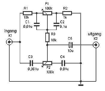
This circuit design implements a passive tone control system utilizing two T-filters to adjust bass and treble frequencies without amplification. The absence of active components means that the circuit does not require an external power source, making it suitable for low-power applications, such as small amplifiers, particularly those with a power rating around 250 mW.
The circuit operates on a line-level signal, ensuring compatibility with standard audio sources. The two T-filters are configured similarly to those found in active tone control circuits, but in this design, the output of the second filter is connected to ground instead of an operational amplifier. This configuration results in a passive attenuation of the audio signal.
The components involved in this circuit include resistors and capacitors, which determine the frequency response and the extent of bass and treble adjustment. The resistors R1 and R3 are both valued at 10 kΩ, while R2 is set at 1 kΩ. The potentiometers P1 and P2, each rated at 100 kΩ, allow for user adjustment of the bass and treble levels, respectively.
Capacitors C1 and C4 are both 10 nF, providing the necessary coupling for the T-filter configuration. C2, with a value of 100 nF, further shapes the frequency response, while C3, at 1 nF, fine-tunes the treble adjustment. The circuit also includes C5, a 10 µF capacitor, which may serve as a coupling capacitor or for DC blocking, ensuring that only AC signals pass through.
In summary, this passive tone control circuit is a straightforward and effective solution for adjusting audio frequencies in low-power applications, providing a simple method for enhancing audio performance without the complexity of active components.Here a simple design for an attractive tone. They operate on a passive principle, ie without amplification. The circuit only weakened and therefore require no power. As can be seen, the circuit is built with two T-filters in the same way as the active bass / treble tone control. Only is the right of the two filters are not at the output of an opamp, but mass. P1 and P2 adjusts the bass to the treble. To hear more bass, you need to P1 in the direction of rotation R1. Contrast to more high tones, you must P2 in the direction of rotation C3. Of course this is not a HiFi sound system, but it is best for small amps like the 250 mW amplifier. Note that the circuit operates at line-levels, they must to get the amp! Parts List R1, R3 = 10kW R2 = 1 kOhm P1, P2 = 100 kOhm C1, C4 = 10 nF C2 = 100 nF C3 = 1 nF C5 = 10 uF 🔗 External reference
Related Circuits
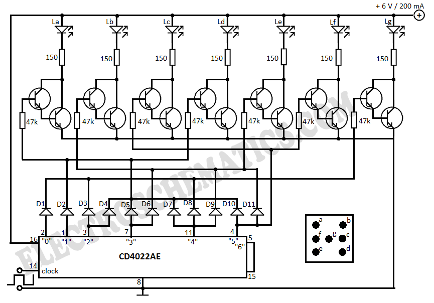
This electronic dice displays results using LEDs arranged to represent each face of a die. The circuit diagram incorporates IC 4022, which functions as a counter. The electronic dice circuit utilizes a combination of integrated circuits and discrete components to...
The LED guard-rail tube, also known as the decorative tube, is an advanced LED illumination product designed for decorative purposes. It utilizes red, green, and blue LEDs as light sources, employing microelectronics and digital technology to create color chasing...
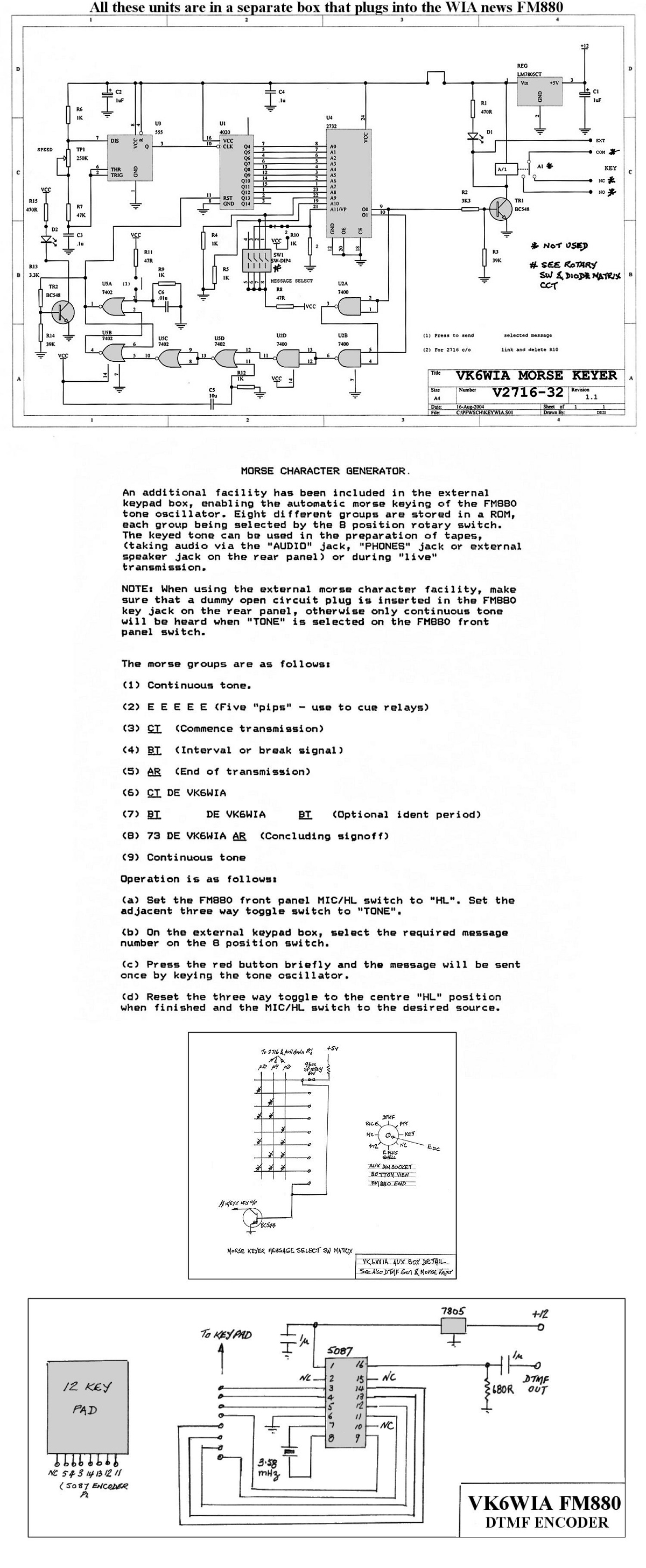
The unit is based on a PHILIPS FM880 link transceiver originally supplied to a Telecom Australia specification for telephone applications in remote areas of Australia. The FM880 is part of a family of equipment that includes the PHILIPS FM828/FM814...
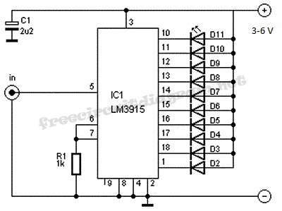
This is a VU meter circuit featuring 10 LEDs. This simple LED VU meter consists of only a few components, yet it serves as an effective indicator for sound levels. The circuit is constructed around an unspecified component. The VU...
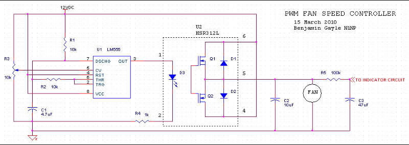
A fan speed controller for computer fans consists of two sections: one for manual speed control and another for automatic temperature-dependent speed control. Additionally, there is a section for a simple LED output indicator. While it is common to...
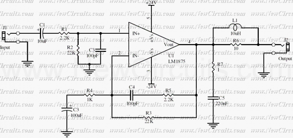
This simple 20 watts audio power amplifier is designed for home-brewed purpose. The L1 should be able to handle a current up to 4A to drive speaker in full load. The distortion is 0.015% @ 1KHz / 20W. This...
Warning: include(partials/cookie-banner.php): Failed to open stream: Permission denied in /var/www/html/nextgr/view-circuit.php on line 713
Warning: include(): Failed opening 'partials/cookie-banner.php' for inclusion (include_path='.:/usr/share/php') in /var/www/html/nextgr/view-circuit.php on line 713