
Homebrew Fan Speed Controller
A fan speed controller circuit typically includes three main components: a manual control section, an automatic control section, and an LED indicator. The manual control section employs a potentiometer to adjust the voltage at the base of a transistor, allowing users to set the fan speed directly. The transistor, configured as a voltage follower, enables a small input current to control a larger output current, effectively allowing the circuit to handle higher loads such as those required by high-performance fans.
The automatic control section utilizes an NTC thermistor to monitor temperature changes. The thermistor is part of a voltage divider, where its resistance decreases as the temperature rises. This change in resistance alters the voltage at the inverting input of an operational amplifier (op-amp). The non-inverting input receives a reference voltage set by another potentiometer, establishing a threshold for minimum fan speed. The op-amp functions as a difference amplifier, outputting a voltage that corresponds to the difference between the two inputs. This output controls a transistor that drives the power transistor, which in turn powers the fans.
The circuit design incorporates a capacitor at the output, which serves a dual purpose: it helps the fans start at lower voltages and acts as a low-pass filter to minimize electrical noise generated by the fan motors. The entire circuit can be assembled on a perfboard using wire-wrap or point-to-point techniques, allowing for flexibility in construction. It is recommended to bench-test the circuit thoroughly before installation to ensure functionality and reliability. This project caters to enthusiasts who prefer a customized solution over commercial fan controllers, providing an engaging experience in electronics assembly and design.A fan speed controller for your computer fans. There are two sections: one for manual speed control, and one for automatic (temperature dependent) speed control. There is also a third section for a simple LED output indicator. Why not just run the fans off the motherboard fan connectors This is what most people should do. However, there are fans out there such as the Vantec Tornado which require more current than the motherboard will supply. This requires an external controller to vary the speed. Some people just want the extra knobs to turn. Why not just buy a fan controller and plug-n-play That is what most people should do. This article is for those who like to tinker and play and burn themselves with soldering irons. It is nice to end up with a working project that you can point to and say "I built that". These projects assume that the reader is somewhat familiar with electronics and has the ability to build circuits from scratch. My projects were built with parts and materials on hand, your available parts and materials may vary.
Breadboarding and testing the circuits before soldering is strongly advised. In case you don`t know what I`m talking about, here is a pic of the automatic speed control circuit breadboarded and under test on the bench: Always bench-test the finished project before installing it in your computer to make sure it works and works like it is supposed to. Use whatever construction method suits you best. These projects worked out well for me using a mix of wire-wrap and point-to-point on perfboard. Do not assume that the way I went about these circuits is the only or best way, there are other ways to accomplish the same thing (please post and discuss The simplest approach is to manually adjust the speed by turning a knob.
This circuit uses a potentiometer to vary the voltage at the base of a transistor, which acts as a voltage follower: the output voltage follows the input voltage. This also acts as a current amplifier, as a small input current at the base is translated to a large input current at the output (up to 3A with the TIP41C transistors I used on this project).
A capacitor on the output helps to start the fan at lower voltages, and acts as a low-pass filter to keep fan motor noise from propagating back into the power supply. This project is for those of you who, like me, are too lazy to be bothered to monitor your system temperature and turn the fan speed up when the temperature goes up.
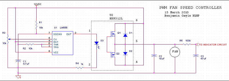
This circuit takes the manual speed controller from above and replaces the potentiometer with an automatic control circuit. The temperature monitoring is done with a NTC thermistor connected to the inverting input of an op-amp.
"NTC" means that as the temperature increases, the resistance decreases. The thermistor is connected in a voltage divider, so that as its resistance changes, the voltage at the input of the op-amp changes. The non-inverting input is connected to a potentiometer to set the reference voltage, which effectively sets the lower limit on the fan speed.
The output voltage follows the difference in voltage at the two inputs. The output is connected to a small transistor which is darlington-connected to a power transistor that acts as a current amplifier, which drives the fans. This circuit is a difference amplifier with negative feedback. As temperature increases, the difference in voltage between the op-amp`s inputs increases. This causes the op-amp`s output voltage to increase, causing the transistor output voltage to increase.
This makes the fans spin faster, which hopefully results in the temperature decreasing. As th 🔗 External reference
Related Circuits
The TRW-24G connector pins are quite small, approximately 1mm apart. To address this issue, an adaptor PCB has been ordered to convert the small connector of the RF module to a standard pin connector. The pin arrangement of the...
Microcontroller-Based Accelerometer Project. Just as a speedometer is a device that measures speed, an accelerometer is a device that measures acceleration. The microcontroller-based accelerometer project utilizes an accelerometer sensor to detect changes in velocity and orientation. This project typically involves...
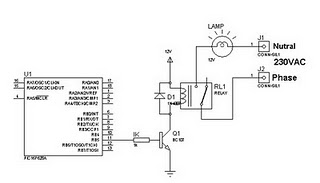
A relay can be controlled using a PIC microcontroller. The circuit illustrates how to control a single relay with the PIC 16F628. When the RB5 port of the PIC is set to high, the relay will activate. This circuit...
The 555 IC is configured in an astable mode, producing a frequency that remains constant and is independent of the duty cycle. The total resistance (Rcharge + Rdischarge, considering the diode) is fixed at 22 kΩ, yielding a frequency...
Atmel Flash devices are well-suited for development due to their ease and speed of reprogramming. They provide ample code space for applications, especially for projects involving the 89Cxx series with the C programming language. Atmel offers a wide selection...
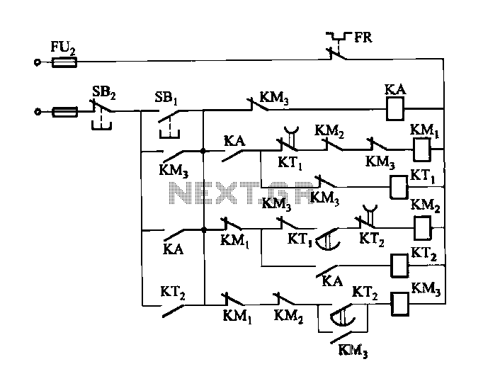
Figure 3-118 illustrates an automatic acceleration control circuit. This circuit employs a male contactor time relay, enabling the motor to start automatically at a low speed before transitioning to high-speed operation. The automatic acceleration control circuit depicted in Figure 3-118...
Warning: include(partials/cookie-banner.php): Failed to open stream: Permission denied in /var/www/html/nextgr/view-circuit.php on line 713
Warning: include(): Failed opening 'partials/cookie-banner.php' for inclusion (include_path='.:/usr/share/php') in /var/www/html/nextgr/view-circuit.php on line 713