
Audio Tube Preamplifier Circuit 6DJ8 / ECC88 SRPP

The described device is an analog voltage measurement system designed for integration into various electronic applications. It utilizes a Stainless DIL 8 package, which is a dual in-line package (DIP) that accommodates eight pins. This compact form factor is suitable for embedding in printed circuit boards (PCBs) and is commonly used in consumer electronics, industrial applications, and educational projects.
The core functionality of the device is its ability to measure four independent analog voltage inputs, each capable of operating within a range of 0 to 5 volts. This feature allows for the monitoring of various sensor outputs or other analog signals. The analog-to-digital conversion process within the device translates these voltage levels into digital data, which can be processed or displayed as needed.
The output of the device is transmitted through a standard asynchronous serial link, which is a widely used method for serial communication. This interface allows for easy integration with microcontrollers, computers, or other digital systems. The output data is formatted as four characters, representing the measured voltage levels, making it simple for receiving systems to interpret the information.
In summary, this device serves as a versatile analog measurement tool, providing essential functionality for applications requiring voltage monitoring and data transmission in a compact, efficient package. Its design emphasizes ease of use, compatibility with standard communication protocols, and reliable performance in a variety of electronic environments.This tour, available in Stainless DIL 8 legs, can measure 4 analog voltage independent between 0 and 5 volts, and send the result of this measure in the form of four characters on a standard asynchronous serial link. Its serial output is di.. 🔗 External reference
Related Circuits
This is a simple circuit for a magnetic pickup phono preamplifier. The circuit provides appropriate loading to a reluctance. Here is the circuit: The gain... The magnetic pickup phono preamplifier circuit is designed to amplify the low-level audio signals generated...
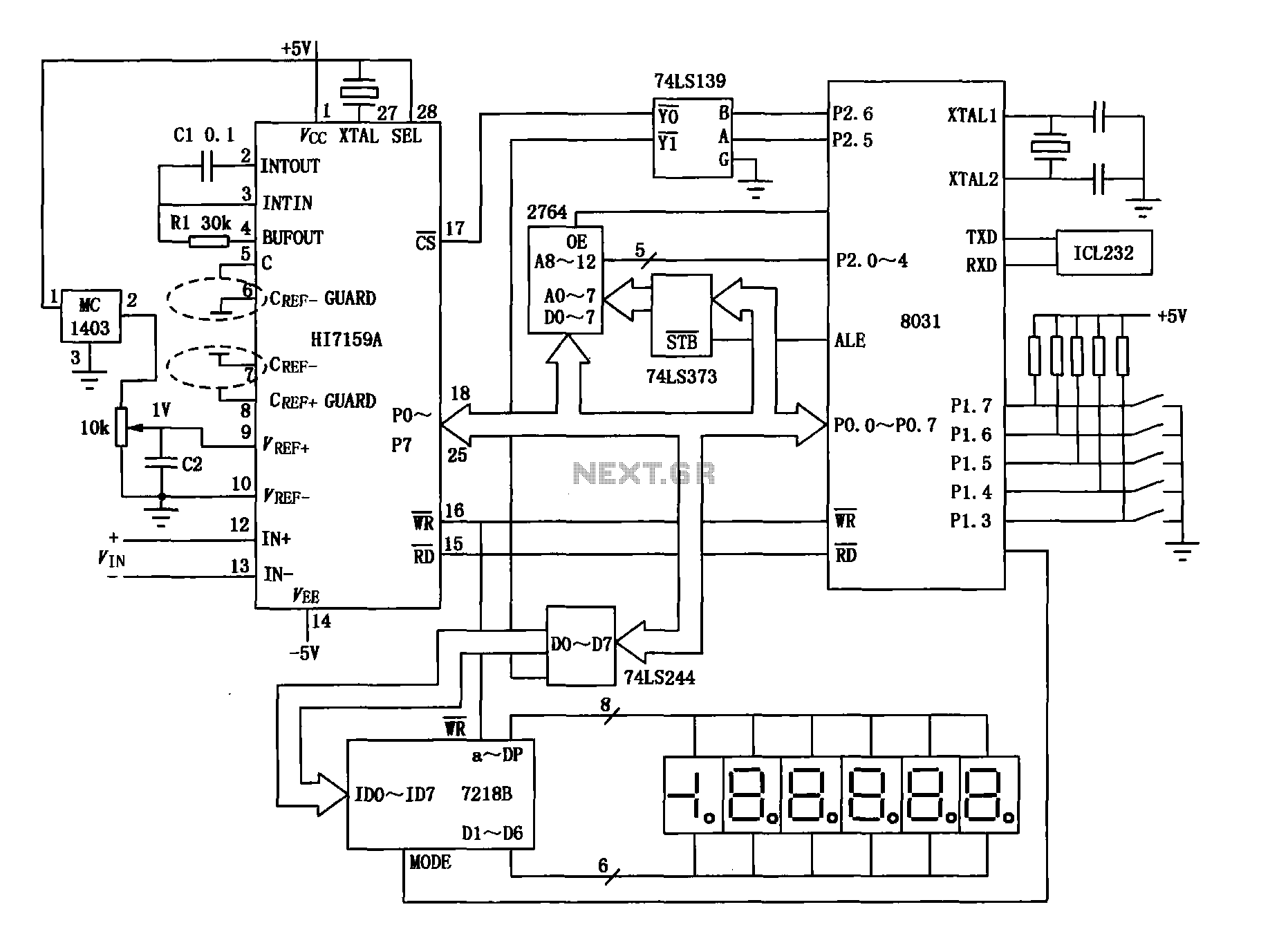
An intelligent digital voltmeter circuit utilizing the HI7159A, 8031 microcontroller, and various other components as illustrated in the figure. The internal circuit incorporates a successive cumulative integrator, digital zero function, low noise BIMOS technology, and other advanced features. In...
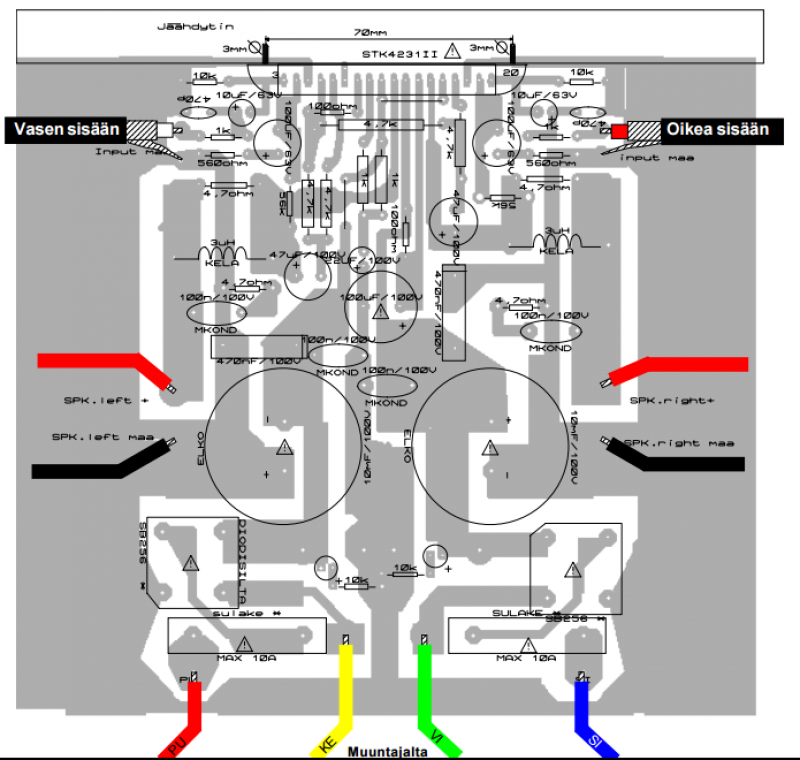
This amplifier is of such high quality that it would be an understatement to call it a HIFI amplifier. According to HIFI-confirmed-Finland, the frequency response must be direct and distortion <1% 20-20 kHz. Our power amplifier circuit meets the above requirements for bandwidth 5Hz - 500 kHz, however, the frequency band is limited to prevent interference. The amplifier meets the requirements for a reference amplifier, which is suitable for measurement and comparison operations. Small 12-24V voltage system amplifiers operating in the power and properties are somewhat modest, for instance, testing decent speakers. The amplifier is also suitable for demanding PA use. When music occurs at shallow close 20Hz sound levels, the whole amplifier power reserve may need to be temporarily used. This happens especially when the low-frequency emphasis equalizer or amplifier is used, for example, TV. Watching a movie with lots of sound effects, if the power is not enough in that situation, the sound from the speakers is distorted, reducing the enjoyment of hearing or even damaging the speaker drivers. The distortion of human hearing range is only about 20 Hz-20 kHz. The hi-fi speaker gamut extends at its best to 25kHz and the hearing area of bats "remains" at 150 kHz, so what are the practical benefits of the amplifier's superior frequency characteristics? The power of less than 1% distortion mentioned in the title 220W blue means the so-called total maximum amount of distortion. This includes TIM distortion (Transient intermodulation) as well as IM-distortion (intermodulation-distortion). TIM distortion occurs in connection with high-speed percussion sounds, such as the sound of dishes on drums. If the amplifier's share of this distortion is high, the amplifier will not be able to play the sound clean, but the sound will be distorted. The higher the frequencies the amplifier is capable of playing, the less is TIM distortion. If the amplifier would be able to repeat 600 kHz, distortion would not occur at all. IM distortion means that the amplifier generates excess denominated, the so-called undesirable ghost signals. For example, fed in to 19 kHz. And 20 kHz, consists of the difference between 1kHz. Safety Because this amplifier has AC parts, its construction is permitted only in the technical work of teachers. Even in this case, the device should be checked by experts before connecting it to the network. Although the equipment has been revised, it is worth remembering that even the only speaker outputs may at best affect almost 70V the effective voltage. Therefore, caution is necessary during building and operation. For instance, the speaker terminals should be protected against contact. Building instructions and testing of the amplifier circuit board components will be worth and an amplifier solder test in three stages: 1) The components of the power side, and all the cables signal cables except installed 2) any other circuit board components plus not only hybrid circuit STK 4231 3) STK 4231 placed and cooled, and the input signals the wires connected. Installation of the power-side components and testing should be done carefully. The transformer wires insulation must first be removed carefully or checked that this has already been done. Then the transformer conductors order is checked on the transformer side. The circuit board parts include STK4231II Hybrid, Led green, resistors of different values, ceramic and plastic capacitors, a rectifier, fuse holders and fuses, a coil, line voltage parts, potentiometer, RCA connectors, speaker output screws, and a cooling unit.
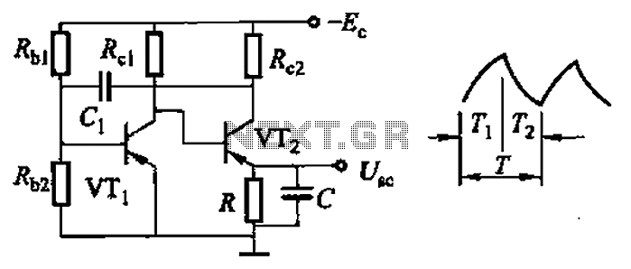
Common non-sinusoidal oscillator circuit, waveform and frequency formula - sawtooth oscillator - use multivibrator. The sawtooth oscillator is a type of non-sinusoidal waveform generator that produces a triangular or sawtooth-shaped output signal. This oscillator is commonly utilized in various applications,...
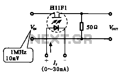
A phototransistor, also referred to as a photosensitive transistor, is primarily utilized as a photosensitive device. It is characterized by its ability to adjust impedance in relation to the intensity of incoming light, similar to that of photosensitive resistors...
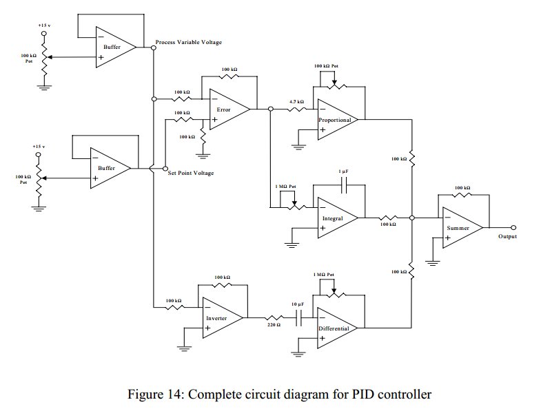
Convert a feedforward operational amplifier PID loop to C code. Assistance is needed for this conversion, as the process is unfamiliar. Input values can be obtained through an ADC, such as voltage or current, but coding a feedforward PID...