
converting circuits to c
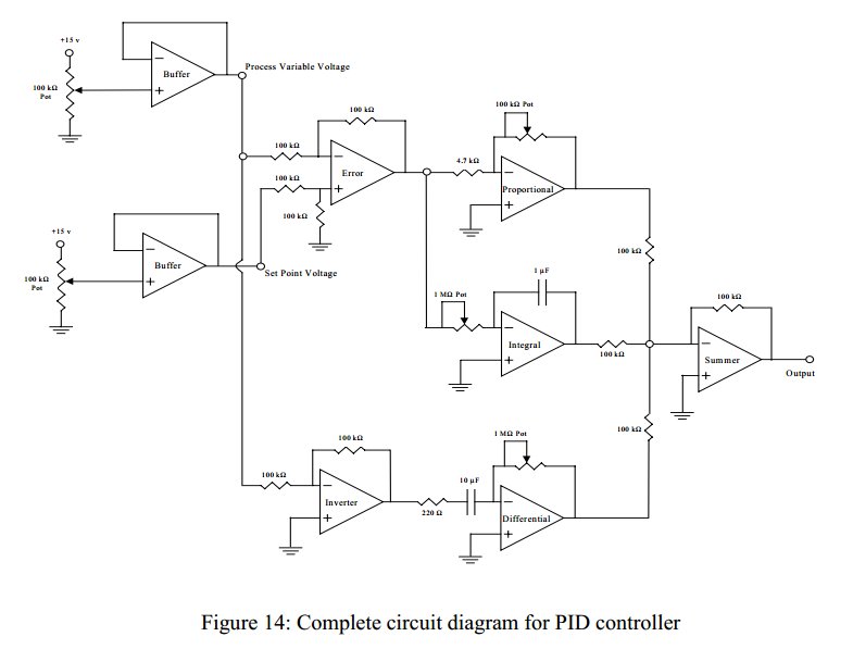
The task involves converting a feedforward operational amplifier PID loop into C code, which necessitates a clear understanding of both the operational amplifier's behavior and the principles of PID control. The feedforward PID controller combines three elements: proportional (P), integral (I), and derivative (D) control, which are essential for optimizing system performance.
In this context, the proportional component amplifies the error signal by a constant factor K, providing an immediate response to the current error. The integral component accumulates past errors over time, ensuring that the steady-state error is minimized. The derivative component predicts future errors based on the rate of change of the error signal, allowing the system to react more swiftly to changes.
To implement this in C, the following steps are recommended:
1. **Define Input Variables**: Establish variables to hold the input values obtained from the ADC, such as voltage and current readings.
2. **Initialize PID Parameters**: Set constants for the proportional gain (Kp), integral gain (Ki), and derivative gain (Kd). These parameters can be tuned based on the specific application requirements.
3. **Create Function for PID Calculation**: Develop a function that calculates the PID output. This function should:
- Compute the proportional term by multiplying the current error by Kp.
- Update the integral term by accumulating the error over time and multiplying it by Ki.
- Calculate the derivative term by determining the difference between the current error and the previous error, dividing it by the time elapsed, and multiplying by Kd.
4. **Implement Feedback Loop**: Integrate the PID function within a loop that continuously reads the ADC inputs, computes the PID output, and applies the output to the system (e.g., controlling a motor or adjusting a valve).
5. **Discretization**: If necessary, apply the bilinear transform to convert continuous PID parameters into discrete values suitable for implementation in the C environment.
6. **Testing and Tuning**: After coding, the system should be tested extensively to ensure stability and performance. Tuning the PID parameters may be required to achieve the desired response characteristics.
By following these steps, a comprehensive C implementation of a feedforward operational amplifier PID loop can be achieved, facilitating efficient control of various systems.Convert a feedforeward opamp PID loop to C code I am trying to do such a conversion and honestly, have no idea where to start. I can get all input values through an ADC, voltage, current, whatever, but coding a feedforeward PID is a little new to me.
Any ideas Are you sure "PID" is the right tag for your questi on Its current description is exclusively about "process IDs". Perhaps your question could be made a bit more verbose. Kerrek SB Nov 15 `12 at 19:26 PID in this context is probably a proportional-integral-differential controller. And op-amp is an operational amplifier. So, as the title suggests, the question is somehow related to how to code up a simulation of an operational amplifier with a feed-forward loop in C.
And it is sufficiently long since I last thought about these terms that I`ve not got a clue on how to go about solving the problem. Jonathan Leffler Nov 15 `12 at 19:39 @JonathanLeffler My first idea is simply making a function that sums a function, its derivative and its integral.
Isn`t that a solution user529758 Nov 15 `12 at 19:43 @H2CO3: pass ” I`d need to think harder than I`ve thought in nearly 30 years about how op-amps are characterized, and we`d need to know how the feed-forward loop is connected, and. generally, we`d need a lot more information than we have. And then there`d be issues with how to code. There are whole languages for circuit simulation, though they may be more commonly for microchip work than this which I`d characterize as `macrochip` (or discrete devices rather than a chip at all).
Jonathan Leffler Nov 15 `12 at 19:46 I think this is described first in "s-domain circuit analysis" and then the result can be discretised with eg. bilinear transform to z-domain. From that point on, the c algorithm is easy. P in the PID means amplifying input by factor K. D means taking successive samples from the input stream, multiplying them with weights b1, b2, b3 (taking e.
g. 3 last samples) and I means feedback loop, where one adds to the result N last results of the circuit again with some weights a1, a2, a3. Aki Suihkonen Nov 15 `12 at 20:31 🔗 External reference
Related Circuits
This circuit enables the brake light to flash. The default behavior occurs when power is supplied to the circuit or when the brake is engaged. The timer IC (IC2) drives current to the transistor (Q2), producing an oscillating output...
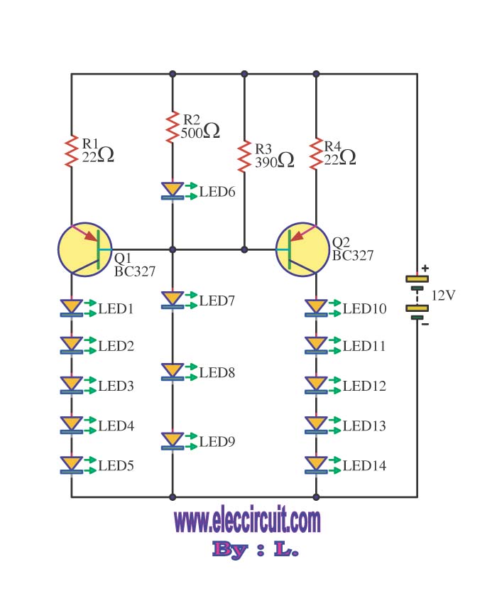
This is a simple game show timer designed for beginners. The power source can be a standard 12-volt lantern battery or a battery pack made from C or D cells. The lamps used can be regular flashlight bulbs; the...
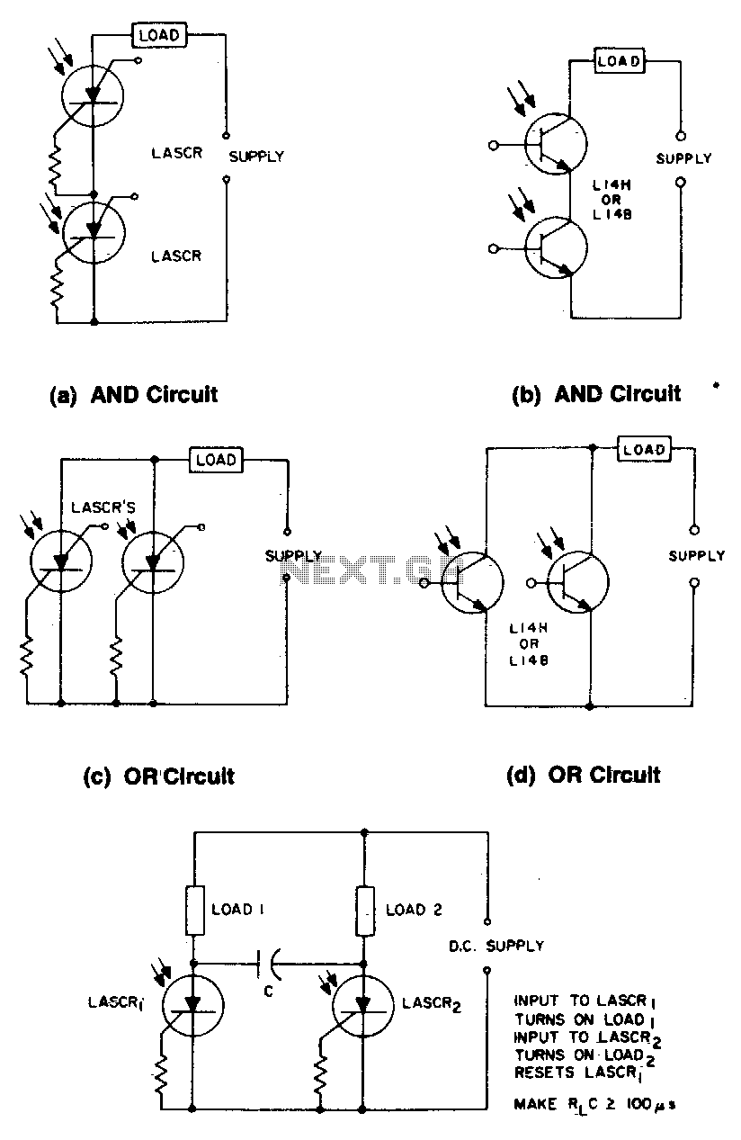
These circuits illustrate some of the common logic functions that can be implemented. The provided circuits serve as examples of fundamental logic functions utilized in digital electronics. Logic functions are the building blocks of digital systems, enabling the execution of...

A field strength meter utilizing a biased Schottky detector employs a temperature-compensated Schottky diode within an amplified, untuned field strength indicator powered by two AA cells. This device indicates the relative field strength of RF fields ranging from a...
Commercial FM demodulation occurs at an intermediate frequency (IF) of 10.7 MHz. With a frequency deviation of ±75 kHz, the deviation of the IF carrier is approximately ±0.7%. This deviation allows for the conversion of FM to AM or...
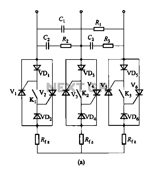
Figure 16-48 (a) illustrates the introduction of a six thyristor three-phase AC switching circuit, while Figure 16-48 (b) depicts the implementation of three triac circuits. These configurations are suitable for motors and other inductive loads. The six thyristor three-phase AC...