
Optical attenuation control circuit
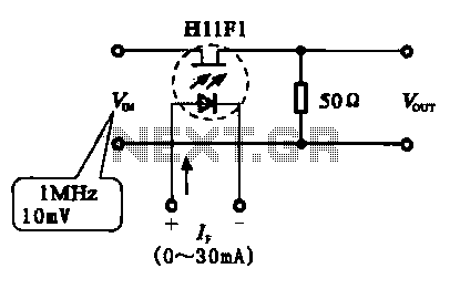
It is extensively employed in optocouplers and specialized circuits. The provided figures illustrate various configurations of photoelectric coupling attenuation circuits. Figure 6-2(a) depicts a photoelectric controller circuit, which includes a phototransistor and a resistor string forming a voltage divider circuit. In this setup, the phototransistor exhibits low impedance, resulting in increased attenuation within the circuit. Figure 6-2(b) presents a fixed resistor circuit where the position of the photosensitive device is exchanged. Here, the impedance of the phototransistor is reduced, leading to a decrease in the amount of attenuation. Figure 6-2(c) displays a practical implementation of the circuit shown in (b).
The phototransistor operates based on the principle of light modulation, where incident light generates electron-hole pairs within the semiconductor material. This process allows the device to conduct current in response to light exposure, effectively turning light signals into electrical signals. The design of the circuit can significantly impact the performance of the phototransistor, particularly in terms of response time, sensitivity, and linearity.
In practical applications, the choice of resistor values in the voltage divider circuit is crucial, as it determines the operational range of the phototransistor. A lower resistance value in the voltage divider will increase the circuit's sensitivity to light changes, while a higher resistance will reduce sensitivity, allowing for more stable readings in varying light conditions.
Furthermore, the configuration of the phototransistor in relation to other components, such as operational amplifiers or microcontrollers, can enhance its functionality in complex systems. By integrating the phototransistor with additional circuitry, it is possible to create advanced light detection systems used in automation, safety devices, and communication systems, where precise control and responsiveness to light variations are essential.
Overall, the phototransistor serves as a fundamental component in various electronic applications, leveraging its unique properties to facilitate the conversion of light into usable electrical signals. Its versatility and effectiveness make it a key element in modern electronic design.Phototransistor also called phototransistor, it is more commonly used as a photosensitive device, which is characterized by photosensitive resistors and photodiode same impedance can be adjusted according to the size of their own light intensity. It is widely used to optocouplers and special circuits. Figure 6-2 shows the photoelectric coupling attenuation circuit, Country 6-2 (a) as shown in the circuit photoelectric controller and phototransistor 500 kfl of a resistor string associated voltage divider circuit, the impedance of the phototransistor is small the amount of attenuation circuit increases. Figure (b) shows a fixed resistor circuit and the photosensitive exchange position of the device, the impedance of the phototransistor becomes smaller, the attenuation amount is reduced.
Figure (c) shows a circuit (b) shows the practical circuit circuit.
Related Circuits

This design circuit is for a simple 27MHz transmitter that produces a carrier signal. The circuit generates an unmodulated 27MHz signal, which can be received by a compatible receiver. The transmitter operates as a basic crystal oscillator, with the...
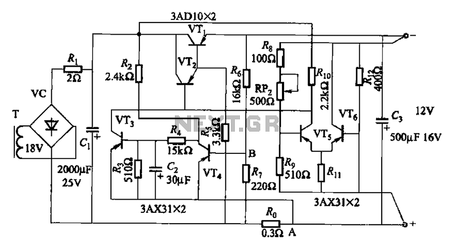
The circuit features a current protection mechanism utilizing transistors VTa, VT4, and a sense resistor Ro. When an overcurrent or short-circuit fault occurs, the power supply cannot resume normal operation because the conduction condition of VT3 remains unchanged, resulting...
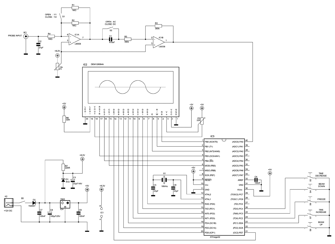
A few months ago as I was surfing on the net, I saw an oscilloscope based on PIC18F2550 microcontroller and a KS0108 controller based graphical LCD. That was Steven Cholewiak's web site. I had never seen before so amazing...
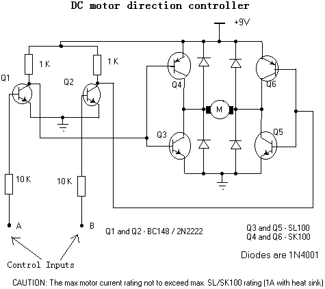
For controlling a small DC motor, such as the one found in a tape recorder, Q1 and Q2 are in saturation when both points A and B are HIGH. Component: .. To control a small DC motor effectively, a circuit...
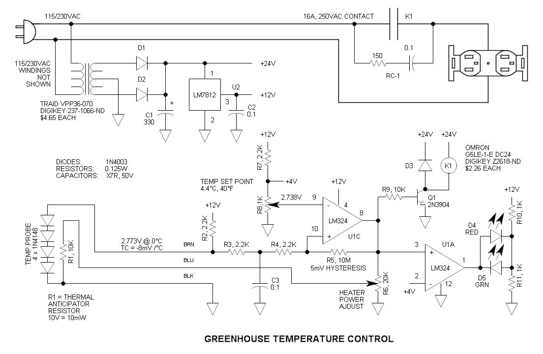
This circuit consists of four 1N4148 diodes connected in series with a thermal anticipation resistor (R1) heat-shrunk together at the end of a three-wire signal cable, which is visible in some photos. The thermal anticipation resistor is an old...
This circuit utilizes the AD639 universal trigonometric function generator from Analog Devices to transform a triangle waveform, which serves as the fundamental waveform of the VCO, into a low-distortion sine wave. By operating the AD639 in its frequency tripler...
Warning: include(partials/cookie-banner.php): Failed to open stream: Permission denied in /var/www/html/nextgr/view-circuit.php on line 713
Warning: include(): Failed opening 'partials/cookie-banner.php' for inclusion (include_path='.:/usr/share/php') in /var/www/html/nextgr/view-circuit.php on line 713