
audio visual ringer circuit diagram

The circuit design for the additional telephone ringer is straightforward and effective, providing both auditory and visual notifications for incoming calls. The integration of the BA8204 or ML8204 IC simplifies the design, as it minimizes the number of required external components, thereby enhancing reliability and reducing assembly complexity. The use of a diode bridge for rectification ensures that the AC ringing signal is converted to a usable DC voltage, which is essential for powering the audio output stage.
Resistor R1 serves as a current limiter for the LED indicator, ensuring that it operates within safe limits while providing a clear visual alert. The combination of capacitors C1 and C2 in conjunction with the diode bridge allows for effective smoothing of the rectified signal, which is crucial for stable operation of the audio ringer.
The audio output, which is modulated by the adjustable resistors R3, R4, and R5, allows for customization of both the sensitivity and frequency characteristics of the ringer. This feature is particularly beneficial in environments where varying levels of ambient noise may affect the audibility of the ringer. The piezo-ceramic sound generator is chosen for its high efficiency and compact size, making it suitable for integration into various settings.
In summary, this additional telephone ringer circuit offers a practical solution for enhancing notification of incoming calls in separate rooms, with the flexibility for users to tailor the sound output to their preferences. Careful selection of component values and configuration allows for a versatile design that meets the needs of diverse applications.Many a times one needs an ex- tra telephone ringer in an ad- joining room to know if there is an incoming call. For example, if the telephone is installed in the drawing room you may need an extra ringer in the bedroom.
All that needs to be done is to connect the given circuit in parallel with the existing telephone lines using twin flexible wires . This circuit does not require any external power source for its operation. The section comprising resistor R1 and diodes D5 and LED1 provides a visual indication of the ring. Remaining part of the circuit is the audio ringer based on IC1 (BA8204 or ML8204). This integrated circuit, specially designed for telec- om application as bell sound generator, requires very few external parts. It is readily available in 8-pin mini DIP pack. Resistor R3 is used for bell sensitivity adjustment. The bell frequency is controlled by resistor R5 and capacitor C4, and the repeat frequency is controlled by resistor R4 and capacitor C3.
A little experimentation with the various values of the resistors and capacitors may be carried out to obtain desired pleasing tone. Working of the circuit is quite simple. The bell signal, approximately 75V AC, passes through capacitor C1 and resistor R2 and appears across the diode bridge comprising diodes D1 to D4.
The rectified DC output is smoothed by capacitor C2. The dual-tone ring signal is output from pin 8 of IC1 and its volume is adjusted by volume control VR1. Thereafter, it is impressed on the piezo-ceramic sound generator Disclaimer: All the information present on this site are for personal use only.
No commercial use is permitted without the prior permission from authors of this website. All content on this site is provided as is and without any guarantee on any kind, implied or otherwise. We cannot be held responsible for any errors, omissions, or damages arising out of use of information available on this web site.
The content in this site may contain COPYRIGHTED information and should not be reproduced in any way without prior permission from the authors. 🔗 External reference
Related Circuits
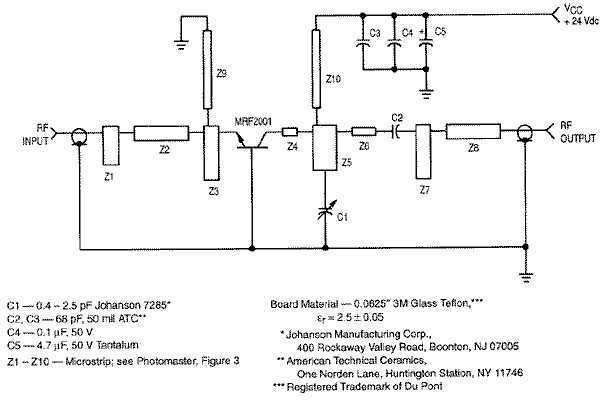
RF amplifier circuit diagram, delivering 1W for 2.3GHz, built based on MRF2001. This RF amplifier provides approximately 1 Watt power output with a minimum gain of 8 dB at a 24V voltage supply. The frequency can be tuned from...

This high voltage source consists of an inverter built around a transistor that generates pulses of 150V. These pulses are supplied to an inverter made of a thyristor and a capacitor, which is connected in series with transformer T2....

The article presents a circuit that can be used for indicating the riding speed of a bicycle. The bicycle speedometer circuit explained here utilizes standard components such as transistors and LEDs to effectively display a clear 10-step, accurately calibrated...

A simple ionization smoke detector with interconnect and timer alarm circuit can be constructed using the A5367 low-current, CMOS circuit, which provides all essential features for an ionization-type smoke detector. This CMOS IC, manufactured by Allegro MicroSystems, includes interconnect...

A band-stop filter (BSF) utilizing an integrated operational amplifier is designed to suppress signals within a specific frequency band, allowing signals outside this band to pass with minimal attenuation. This configuration is achieved through a two-stage network, which employs...
An electrocardiogram (ECG), also known as EKG (derived from the German term Elektro-Kardiographie), is an electrical recording of the heart utilized in diagnosing heart disease. This application employs a DrDAQ Data Logger to read and store electrocardiograms. British physiologist...
Warning: include(partials/cookie-banner.php): Failed to open stream: Permission denied in /var/www/html/nextgr/view-circuit.php on line 713
Warning: include(): Failed opening 'partials/cookie-banner.php' for inclusion (include_path='.:/usr/share/php') in /var/www/html/nextgr/view-circuit.php on line 713