
bicycle speed indicator circuit explained

The bicycle speedometer circuit operates on the principle of converting the mechanical rotation of the bicycle wheel into an electrical signal. The dynamo, typically mounted on the bicycle frame, generates an alternating current (AC) voltage as the wheel turns. This AC signal is then rectified using a diode bridge to convert it into direct current (DC), which is necessary for the subsequent processing.
The core of the circuit involves a microcontroller or a comparator circuit that interprets the varying voltage levels from the dynamo. By calibrating the circuit, it can map the voltage levels to specific speed ranges. For instance, the circuit can be designed to illuminate different LEDs corresponding to speed intervals, providing a visual indication of the bicycle's speed.
Transistors are used in this circuit as switches or amplifiers to control the LEDs. When the voltage reaches a certain threshold, the transistor activates, allowing current to flow to the corresponding LED. This arrangement can create a 10-step LED display, where each LED represents a specific speed range, enhancing the user’s ability to monitor speed at a glance.
To ensure accuracy, the circuit may include a feedback mechanism or a calibration feature that allows users to adjust the sensitivity based on tire size or other factors affecting speed measurement. Additionally, the design may incorporate a low-pass filter to smooth out any fluctuations in voltage readings, providing a more stable and reliable speed indication.
Overall, this bicycle speedometer circuit exemplifies a practical application of basic electronic components to create an effective speed measurement tool, enhancing the cycling experience through real-time feedback on performance.The article presents a circuit that can be used for indicating the riding speed of a bicycle. The circuit of a bicycle speedometer explained here uses ordinary components like transistors and LEDs and yet succeeds in displaying a distinct 10 step, accurately calibrated linear reading, corresponding to the instantaneous speed of the bicycle wheels. The source is basically derived from a dynamo that generates electricity levels directly proportional to the speed of the bicycles rotating wheel, this varying potential is translated by the circuit into the corresponding reading through the illuminated LEDs..
🔗 External reference
Related Circuits
This circuit operates at potentially lethal 220V AC mains voltage. The circuit should be built and used only by individuals who know how to safely work with such dangerous voltages and how to construct the circuit to ensure safety....
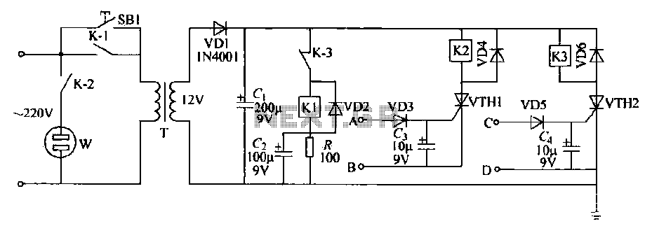
This schematic circuit features two alarm outputs controlled by a timer using thyristors. The system can be turned on or off and will shut down after the power supply is interrupted. It employs a transformer on the primary side...

The circuit of this 30W audio amplifier produces clear audio output quality. The circuit module does not have any improvements. It utilizes a Darlington pair in the transistor configuration. The 30W audio amplifier circuit is designed to deliver high-fidelity sound...

The TDA2030 amplifier circuit is suitable for driving low-frequency subwoofer speakers in home theater systems. The TDA2030 is a monolithic integrated circuit designed for use as a low-frequency class AB amplifier. This TDA2030 amplifier design requires a dual power...

A typical silicon-controlled rectifier (SCR) requires a trigger current to latch on. Once the device is latched, the current flowing through the SCR is determined only by the external component values. The SCR lacks the ability to limit current...
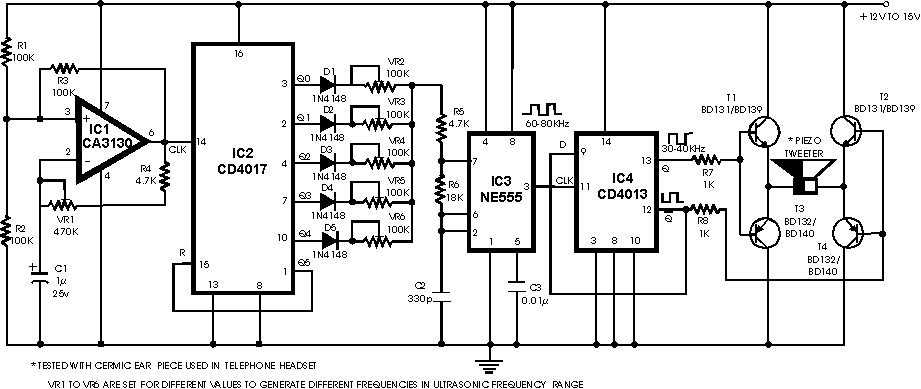
There are many ultrasonic pest repellent devices available on the market, but a major drawback is that their power output is low and their effectiveness suffers. Ultrasonic pest repellent devices utilize high-frequency sound waves to deter pests such as rodents...