
Second-order active band stop filter circuit
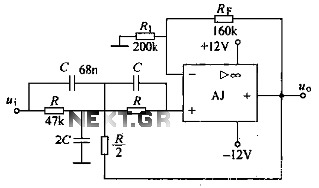
The band-stop filter (BSF) is a critical component in various electronic applications where it is necessary to eliminate unwanted frequencies while preserving the integrity of other signals. The design typically consists of a combination of resistors, capacitors, and operational amplifiers that work together to create a notch in the frequency response at the desired frequency range.
In this configuration, the operational amplifier serves as the active element, providing gain and allowing for precise control over the filter characteristics. The dual op-amp arrangement enhances the filter's performance by enabling the implementation of more complex filtering techniques, such as feedback and feedforward paths, which can improve stability and selectivity.
The two-stage network in the band-stop filter consists of a series of reactive components that define the filter's cutoff frequencies and the depth of attenuation at the notch frequency. The T-phase ratio arithmetic circuit plays a vital role in determining the phase response of the filter, ensuring that the output maintains the desired characteristics over the specified frequency range.
Overall, the integrated operational amplifier band-stop filter is an essential tool in signal processing, audio engineering, and communication systems, where it is crucial to eliminate specific interference while allowing other signals to pass through unaffected. The design's effectiveness is largely dependent on the precise selection of component values and the configuration of the operational amplifiers used in the circuit. Band-stop filter (BEF) integrated operational amplifier, such electrical road performance and a bandpass filter contrary, that in a certain band, the signal can not be (or has been greatly attenuated or suppressed), while in the remaining frequency Fan Wai, signals can be passed. After two-plus network level T-phase ratio arithmetic circuit, it constitutes the basic second-order active band-stop filter BEF.
Band stop filter as shown in FIG. FIG integrated operational amplifier AJ dual op amp
Related Circuits
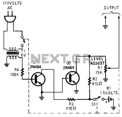
This generator circuit utilizes an overdriven amplifier to generate a 60 Hz square wave from the 60 Hz AC line. The circuit is suitable for line-operated applications as a clock source. The generator circuit operates by leveraging an overdriven amplifier...
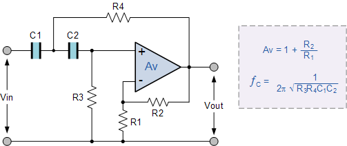
Electronics tutorial about active high-pass filters, including their high-pass filter frequency response, op-amp voltage gain, and active filter construction. Active high-pass filters are essential components in electronic circuits, designed to allow signals with frequencies higher than a certain cutoff frequency...
One of the critical components is a PWM speed controller, allowing for fine speed adjustments instead of just an "on" mode that runs at full power. This is important for safety. A basic stamp microcontroller was purchased, which includes...
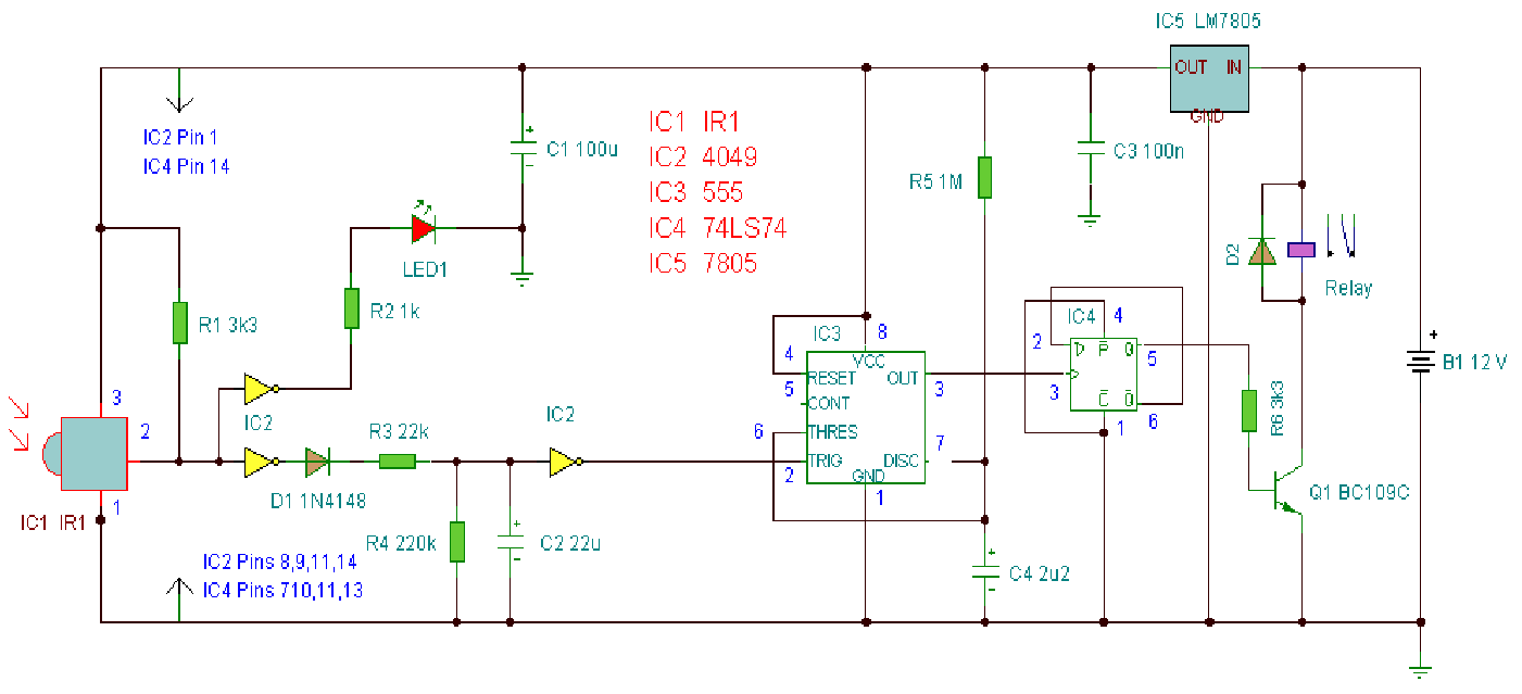
A computerized infrared remote project is a simple device designed for recording and playing back streams of infrared data, specifically the codes transmitted by remote controls. Software is provided for use in both DOS and Windows environments, along with...
SPI Integrated Circuit Bus, IC Buses, an IC, Chip-to-Chip Bus Serial Peripheral Interface, Integrated Circuit Bus types, and IC Bus Electrical Interface Descriptions. The Peripheral Interface (SPI) circuit is a. The Serial Peripheral Interface (SPI) is a synchronous serial communication...
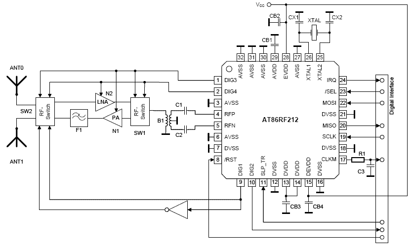
The electronic motor speed controller circuit includes a wireless remote control transmitter circuit and a wireless remote control receiver circuit, as illustrated in the accompanying chart. The wireless remote control transmitter circuit comprises a micro-power wireless remote control transmitter...