
Auto Alarm

The described circuit functions as a security alarm system controlled by an external key switch (SI). The initial operation of SI initiates a programmable delay period ranging from 0 to 45 seconds, allowing users to enter a secure area without triggering the alarm. During this interval, LED1 serves as a visual indicator, illuminating in green to signify that the system is in a standby state.
Once the delay period elapses, LED1 changes to red, signaling that the alarm system is now armed. This change in LED color is crucial for user awareness, ensuring that individuals are informed of the system's status. The system employs multiple sensors (S2 through S4 and S5 through S6), all configured as normally open (NO) contacts. When any of these sensors detect an intrusion by closing the circuit, they pull pin 2 of the operational amplifier (U2) low. This action triggers relay K1, which activates the alarm.
The alarm's duration is adjustable and is determined by the values of resistor R4 and capacitor C2, which form an RC timing circuit. The time constant of this circuit dictates how long K1 remains activated, thus controlling the length of time the alarm sounds. After the predetermined time has elapsed, K1 is deactivated, returning the circuit to its initial state and preparing it for subsequent operations.
To reset the system manually, the user must operate the key switch (SI) again. This feature enhances the security of the system, ensuring that unauthorized access cannot easily reset the alarm without the appropriate key. Overall, this alarm system design effectively integrates user control and security features, providing a reliable solution for intrusion detection. SI is external key switch. The alarm allows a 0- to 45-s delay after SI is operated before the circuit is armed. During this per iod, LED1 lights green. After this delay, LED1 lights red, which indicates that the circuit is armed. Then, sensors S2 through S4 -(NO) or S5 through S6 (NO) pull pin 2 of U2 low, which activates K1 and sounds the alarm. The alarm sounds for a duration determined by R4 and C2. After this time, K1 releases and the circuit is again ready. Manual reset is via the key switch, SI.
Related Circuits
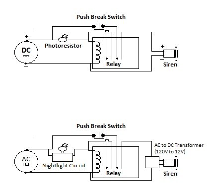
Building a DIY Alarm System: The Concept. An alarm system serves to protect property, whether it be a room, vehicle, or outdoor area. The primary function of the alarm system is to alert the designated administrator of any intrusion...
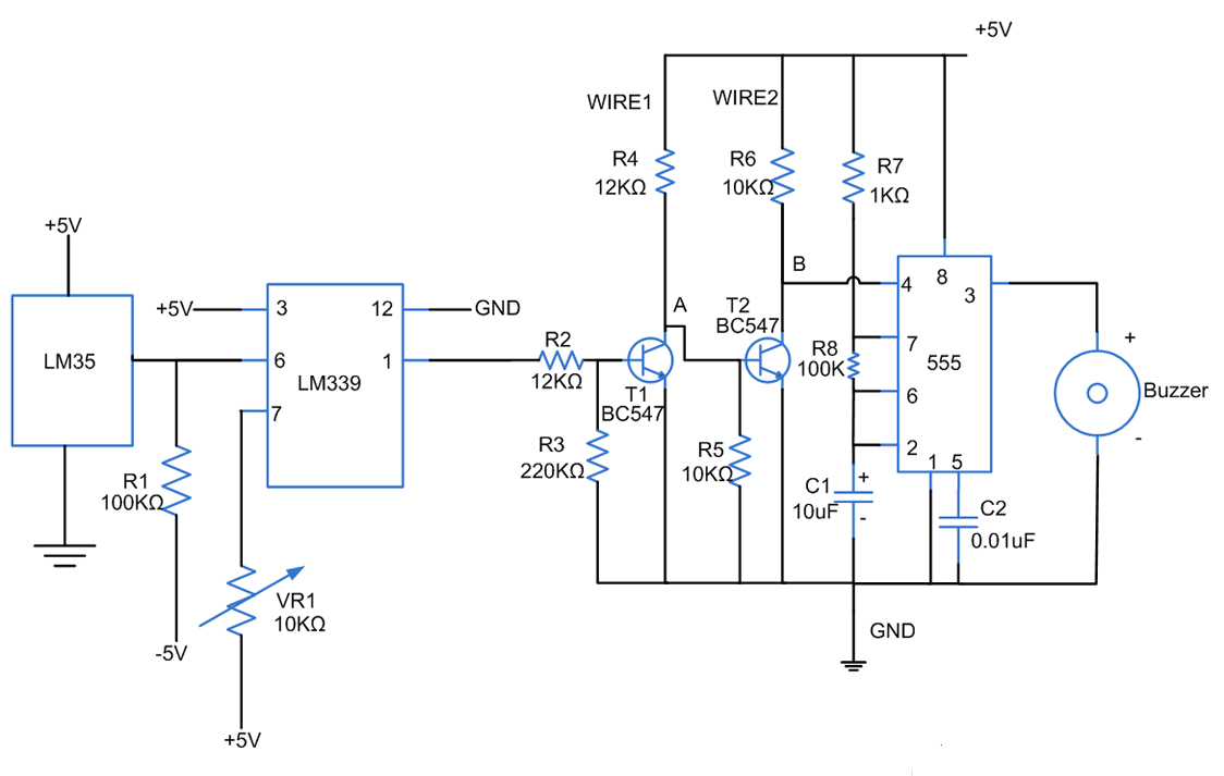
Fires can occur for several reasons, such as forgetting to turn off equipment like irons. A fire alarm circuit with a temperature sensor may be one option to secure homes from fire hazards. There are also fire alarm circuits...
This circuit automatically activates a night lamp when the bedroom light is turned off. The lamp stays illuminated until the light sensor detects daylight in the morning. A super-bright white LED is utilized as the night lamp, providing bright...
Here's a circuit to create a buzzcoil using a standard automotive ignition coil. A 556 dual timer is used to establish the frequency and duty cycle of the coil current. One of the timers is used as an oscillator...

A certain part of this circuit is directly connected to the AC mains; therefore, do not touch it while in operation. It is essential to exercise extreme caution when handling the AC mains supply during the construction of this...
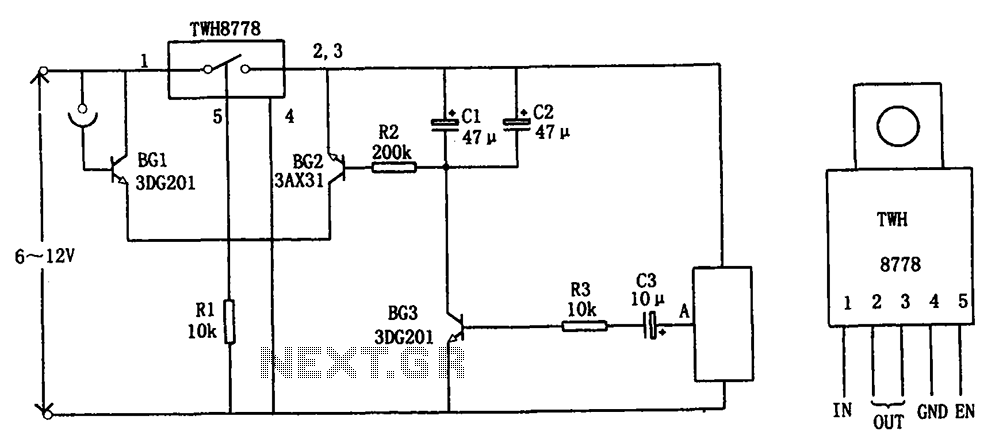
The circuit illustrated in FIG X pertains to automatic circuitry for US recorders. It primarily utilizes a new power switching device, TWH8778, which simplifies the design and eliminates the need for extensive debugging. The TWH8778's configuration and pin functions...