
Automotive ignition coil
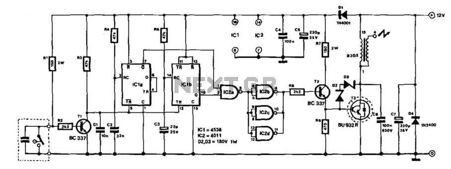
This circuit design employs a 556 dual timer IC to create a buzzcoil using an automotive ignition coil, providing a practical application for generating high-voltage sparks for ignition purposes. The 556 timer is configured in a manner that allows one timer to function as an oscillator, producing a rectangular waveform at a frequency of approximately 200 Hz. This waveform is crucial for controlling the gate of the IRF740 MOSFET, which acts as a switch to enable current flow through the ignition coil.
The second timer is utilized to manage the operation of the oscillator based on the status of the breaker points in the ignition system. When the breaker points are closed, they create a low signal that allows the first timer to generate a high output at pin 9. This output is inverted and used to control the reset line of the second timer, ensuring that the output at pin 5 remains low while the breaker points are open.
Timing components, including a 15K resistor, a 4.7K resistor, and a 0.33 µF capacitor, are selected to establish the desired frequency and duty cycle for the second timer. The positive interval is set to approximately 4 milliseconds while the negative interval is about 2 milliseconds. During the positive interval, the gate of the MOSFET is driven high, allowing the current through the ignition coil to reach approximately 4 amps. This current generates around 80 millijoules of energy, which is subsequently released as a spark when the output of the timer transitions low, thereby turning off the MOSFET.
To protect the MOSFET and ensure reliable operation, a 12-volt zener diode is incorporated at the junction of the 10-ohm and 27-ohm resistors, which prevents the gate voltage from exceeding 12 volts or dropping below -0.7 volts. Additionally, a 200-volt, 5-watt zener diode is connected to the drain of the MOSFET to limit voltage spikes and extend the duration of the spark.
While the circuit is designed to function reliably even with a shorted spark plug, it is important to note that operating the circuit without any load connected may lead to potential failures, as excessive energy may be absorbed by the zener diode. An alternative to the zener diode includes using a transient voltage suppressor (TVS) such as the 1.5KE200A or 1.5KE300A, which may offer improved performance characteristics, albeit with availability considerations.Here's a circuit to create a buzzcoil using a standard automotive ignition coil. A 556 dual timer is used to establish the frequency and duty cycle of the coil current. One of the timers is used as an oscillator to generate the 200 Hz rectangular waveform needed to control the (IRF740 MOSFET) while the second timer switches the oscillator on and off as the breaker points open and close (closed = on). The result is a steady stream of sparks from the ignition coil spaced about 5 milliseconds apart while the breaker points are closed.
Pin 8 and 12 are the threshold and trigger inputs of one timer which are driven by the breaker points and produce an inverted signal at the timer output (pin 9). When the points are closed to ground, pin 9 will be high and visa versa. The signal at pin 9 controls the reset line (pin 4) of the second timer and holds the output at pin 5 low while pin 4 is low and pins 8 and 12 are high (points open). The 15K and 4.7K resistors and 0.33uF capacitor are the timing components that establish the frequecy and duty cycle of the second timer which is about 4 milliseconds for the positive interval and 2 milliseconds for the negative.
During the positive time interval, the MOSFET gates are held high which causes the ignition coil current to rise to about 4 amps. This equates to about 80 millijoules of energy in the coil which is released into the spark plug when the timer output (pin 5) moves to ground, turning off the MOSFET.
A 12 volt zener diode is placed at the junction of the 10 and 27 ohm resistors to insure the MOSFET gate input never goes above 12 volts or lower than -0.7 volts. A 200 volt/5 watt zener is used at the MOSFET drain to limit the voltage to +200 and lengthen the spark duration.
The circuit should operate reliably with a shorted plug, however operating the circuit with no load connected (plug wires fallen off, etc.) may cause a failure due to most of the power being absorbed by the zener. You can also use a transient voltage suppressor (TVS) such as the 1.5KE200A or 1.5KE300A in place of the zener.
It's probably a better part, but hard to obtain. 🔗 External reference
Related Circuits
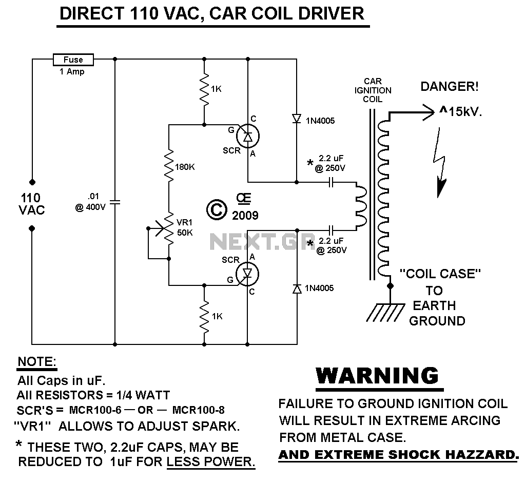
This Spark Can Be Very DANGEROUS, So BE CAREFUL. WARNING: FAILURE TO DO SO: WILL CAUSE THE CASE OF THE COIL TO ALSO BE ELECTRIFIED! NOTE You MUST have a LOAD on the High Voltage Output. With NO LOAD,...
Here is a Tesla coil secondary design: Wind 750 turns of 24-gauge enameled magnet wire onto an 18-inch long piece of 1.9-inch outer-diameter PVC pipe. The large coil has an inductance of approximately 2800 mH and a self-capacitance of...
The description pertains to a specific type of preamplifiers that are designed to amplify the low output of Moving coil heads, enabling their drive to an input PHONO [RIAA] of a preamplifier. Moving coil heads present certain challenges that require...
This electronic ignition circuit is designed to be integrated into a conventional car ignition system. It replaces the original 12-V switching circuit in the primary winding of the ignition coil with a circuit that generates over 100 V. This...
Multi-spark ignition is very useful especially in the case of startings at low temperature and at low rpm range. Basic idea, is to apply to spark plugs instead of only one spark, a spark-burst having big energy. In this...
Tuning a system is typically a challenging task. The user must power the system, observe the spark length, shut it down, adjust the primary tap, restart, and repeat this process until the spark length is optimized. However, using a...