
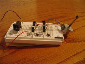
Auto light controller
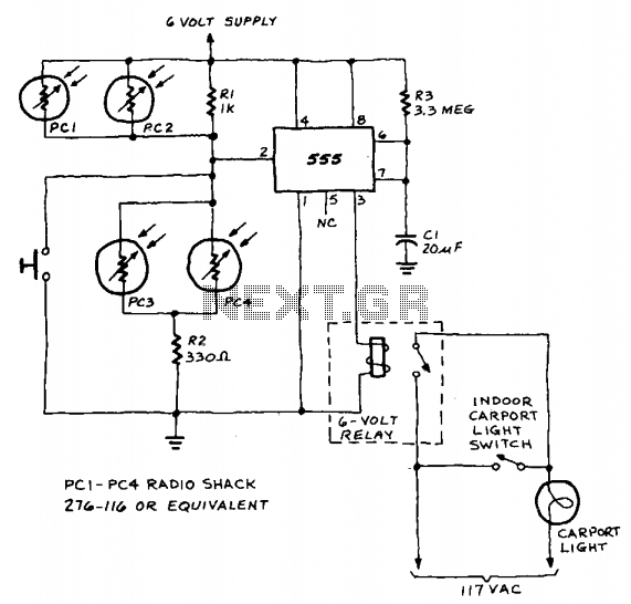
The circuit utilizes a 555 timer IC configured in monostable mode, which is ideal for generating a single output pulse when triggered. The input to the timer is derived from the photoresistors, which serve as light sensors. When ambient light levels are low, the resistance of the photoresistors is high, preventing the timer from triggering. However, when headlights shine on the photoresistors, their resistance drops significantly, allowing a voltage level sufficient to trigger the 555 timer.
The timing interval is determined by the values of the resistor (R) and capacitor (C) connected to the timer. The time period (T) for which the output remains high can be calculated using the formula T = 1.1 * R * C. In this circuit, the chosen R-C values are designed to achieve an approximate duration of two minutes, ensuring that the lights remain on for a sufficient period after being triggered.
Relay RY1 acts as a switch, controlling the power to the lights. When the timer output goes high, it energizes the relay coil, closing the contacts and allowing current to flow to the lights. Once the timer elapses and the output returns to low, the relay is deactivated, opening the contacts and turning the lights off.
This setup is particularly useful in automotive applications where lights need to be activated automatically in response to external light conditions, enhancing safety and convenience. The positioning of the photoresistors at headlight height ensures optimal sensitivity to oncoming vehicles, allowing for timely activation of the lights. The automatic shut-off feature prevents unnecessary battery drain, making the circuit efficient and practical for real-world use.A 555 timer IC, operating in the one-shot mode, is triggered by light striking photoresistors. These normally have a resistance of several megohms but, in the presence of light, that resistance drops to several hundred ohms, permitting current from the six-volt source to flow in the circuit. The R-C combination shown gives an on-time of about two minutes. Photoresistors PC3 and PC4 are mounted at heatlight-height. When headlights illuminate the photoresistor, the timer starts. That actuates a relay, RY1, and the lights are turned on. The lights are automatically turned off when the timer's two minutes are up. 🔗 External reference
Related Circuits
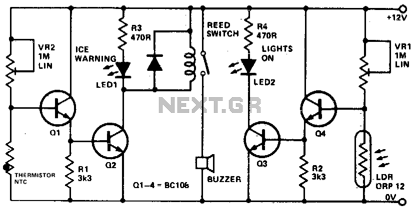
This device informs a driver whether their lights should be activated and warns them if the outside temperature approaches zero degrees Celsius by illuminating an LED and sounding a buzzer. The sensitivity can be adjusted using VR1, and the...
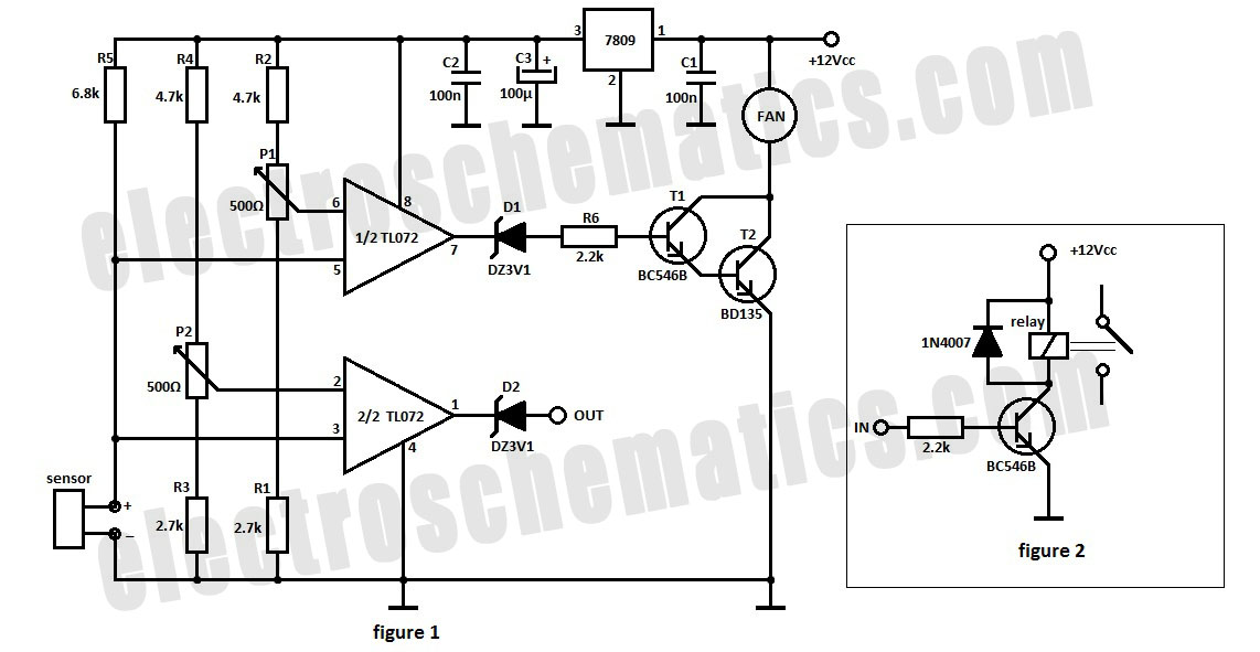
The automatic fan controller circuit depicted in the schematic features two comparators with distinct triggering points that can be adjusted independently. LM135 or... The automatic fan controller circuit is designed to regulate fan operation based on temperature variations. It employs...
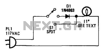
Lamp II is a household lamp. When the switch is in the center position, the lamp operates on half-wave rectified AC; the effective voltage that the lamp receives is reduced, which dims it. Lamp II can accommodate a power...
A pulse motor, commonly known as a stepper motor, is defined as a motor that changes its excitation state according to input pulse signals, allowing it to move forward at a specific angle or distance. If the excitation state...
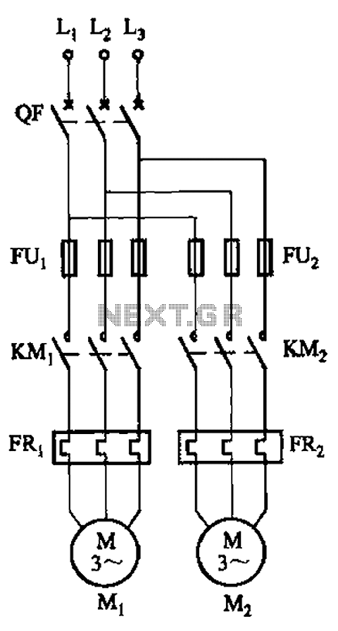
The circuit illustrated in Figure 3-64 operates with switch SA1 in the work position and switch SA2 in the standby position, allowing motor Mi to run while motor Mz remains on standby. In the event of downtime for motor...
Christmas is approaching, and it is the time of year when electronics students and hobbyists consider creating a Christmas circuit for their homes, particularly one that features flashing lights. Numerous circuits and kits are available that can flash various...