
stepper motor controller schematic
The pulse motor, or stepper motor, is a crucial component in various applications that require precise control of angular or linear motion. The operation of a stepper motor is based on the principle of electromagnetic induction, where the motor steps through discrete angles as it receives pulses from a controller. Each pulse corresponds to a specific increment of rotation, allowing for accurate positioning without the need for feedback mechanisms, which is a hallmark of open-loop control systems.
In the context of the two-phase hybrid stepping motor, the design incorporates a stator with multiple windings that are energized in a specific sequence to create a rotating magnetic field. This field interacts with permanent magnets or electromagnetic coils on the rotor, causing it to align with the magnetic field and rotate in discrete steps. The precision of this system is enhanced by the careful control of the pulse frequency, which directly influences the speed and torque of the motor.
The bridge rectifier circuit is an essential part of the power supply for the motor, converting AC voltage from the mains supply into the DC voltage required for operation. The diodes within the circuit are selected based on their forward voltage drop and reverse recovery characteristics to ensure efficient rectification and minimal loss during operation. The rectification process ensures that the motor receives a stable DC supply, which is critical for maintaining consistent performance.
The ball screw mechanism represents a significant advancement in translating rotational motion into linear motion. By utilizing ball bearings within the screw thread, friction is reduced dramatically compared to traditional lead screws, where metal-on-metal contact can lead to excessive wear and heat generation. The rolling motion of the balls allows for smoother and more efficient operation, enabling the system to achieve higher speeds and greater accuracy.
The modular design of the stepper motor controller using GAL16V8 devices allows for flexibility in various applications. This design can be tailored to specific requirements, making it suitable for a wide range of mechanical control systems, from robotics to CNC machinery. The high reliability and low power consumption of the controller ensure that it can operate effectively in demanding industrial environments.
In conclusion, the advancements in stepper motor technology, coupled with innovative control strategies, have led to the development of highly efficient and precise motion control systems. These systems are critical for modern automation and robotics, providing the necessary precision and reliability for a wide array of applications.Pulse motor or stepper motor step motors, foreign, or commonly known as Step motor Stepping motor, Stepper, and so on. To the conventional stepper motor, the stepper motor can be simply defined as, according to the input pulse signal, each time changing the excitation state to move forward at an angle (or length), if not change the excitation state is to maintain
a certain position at rest motor. Broadly speaking, the stepper motor is controlled by the electrical pulse signal brushless DC motor can also be seen as a certain frequency range and control of pulse frequency synchronous speed synchronous motor. Used here is the two-phase hybrid stepping motor, the use of displacement and the number of input pulse signals corresponding to step away from the characteristics of error is not accumulated to form the structure is simple and has a precision open-loop control system, the turret drive control system The operative part.
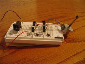
Physical map shown in Figure 1 Rectifier board is used to rectify alternating current into direct current to provide the drive to use, the principle for the bridge rectifier circuit, the schematic shown in Figure 1 age, D2, D4 closed. Circuit constitutes e2, Dl, Rfz, D3 power circuit, the Rfz, formed under the negative on the positive half-wave voltage of the whole wash, e2 is the negative half-week, on D2, D4 plus the forward voltage, D2, D4 conduction; on D1, D3 reverse voltage, D1, D3 closed.
Circuit constitutes e2, D2 Rfz, D4 power circuit, formed on the same is in Rfz the other under the negative half-wave rectifier voltage. Ball is relative to the original in terms of T-shaped screw th. The principle is the rotational variable translation, screw rotation. Ball screw driven slide the rod. Almost with the principle of the screw, but with the ball only. Turn the screw thwhen the original vice more violent friction, including ths and external ths with the ball between the post to become a rolling friction and improve the friction condition, so that the friction is reduced to the original 1 / 50.
Which also allows it to achieve high speed operation. I see an information display is the highest speed of the screw allows the 200m/min. Catching up motor, produced by Japan, its principle is roughly the nut and screw into the ball room, and then added back to the device on the nut, so the ball rolling in in the loop. Abstract: A three-phase application of CAL device design took six working system stepper motor controller, this controller mainly GAL16V8 programmable logic devices, sampling unit and drive the feedback loop composed of three parts, which is characterized by: control precision high (up to 2%), high-speed low-power, high reliability, can independently control the driver object, but also to work in the computer monitor, the controller uses modular design, it can be used in a variety of mechanical control systems.
As we all know, in the stepper motor control system, mainly by the stepper motor, controller, driver object composed of three parts. Early stepper motor controller using discrete components, hardware circuit complexity, unreliable, bulky, expensive, its parameters for different products need to re-design, promotion and application of much more restricted.
SBC came later, showing a single board to replace the stepper motor controller is a trend, but a class of SBC TP801 poor anti-interference, and difficult to run in the industrial field, so this replaces encountered a new difficult. In recent years, MCS296 family microcontroller birth, especially the 8098 microcontroller and development system was a stepper motor control system provides the ideal models, but the control system development cycle is relatively long, and the cost is still too need to high, in order to overcome these shortcomings, we use an advanced programmable logic devices (PLD) in the GAL16V8 design logic circuits, developed a sampling feedback can au
🔗 External reference
Related Circuits

The following circuit illustrates the Bedside Lamp Timer Circuit utilizing the CD4060 integrated circuit (IC). It operates for 30 minutes, with a blinking LED indicating the last 6 minutes of operation. The Bedside Lamp Timer Circuit is designed to provide...
The circuits on this page are for motor controls using Push buttons and would typically be found in commercial and industrial installations. The circuits do not show the wiring of the motors themselves as this depends on the particular...
This document contains a collection of various useful and interesting electronic schematics. Some of these schematics are referenced or included in other documents on this site. Notably absent from this collection is extremely important safety information, which can be...
A few modifications have been made to the dead band and pulse stretcher resistors, and the position feedback potentiometer has been altered to function as a "zero the speed" or "center your transmitter sticks." Additionally, a traditional PNP-NPN H-bridge...
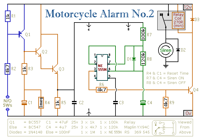
This circuit features an intermittent siren output and automatic reset. It can be operated manually using a key-switch or a hidden switch; but it can also be wired to set itself automatically when you turn-off the ignition. By adding...
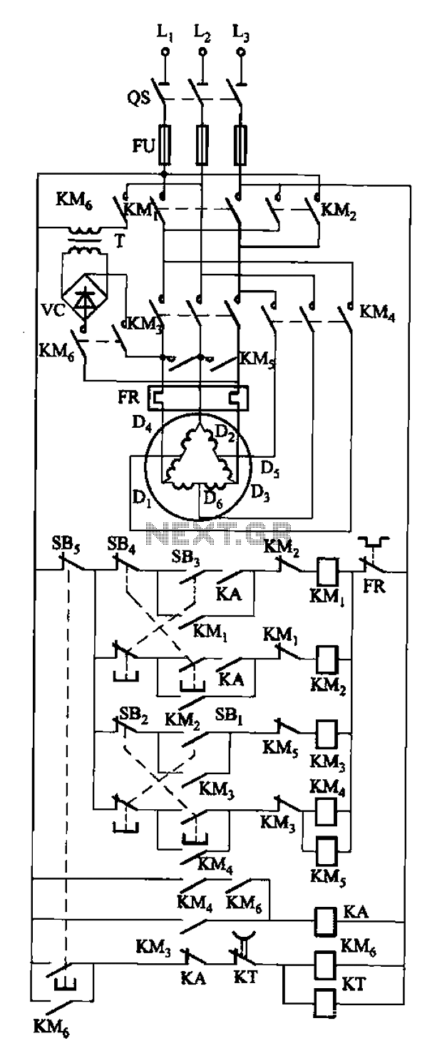
The circuit depicted in Figure 3-108 includes various control buttons: SB3 for the forward button, SI for the reverse button, SBi as the low start button, SB2 for the speed start button, and SBs for the stop button. KMs...