
Automatic Fan Controller Circuit
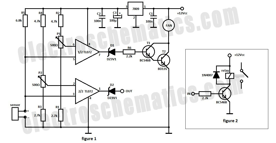
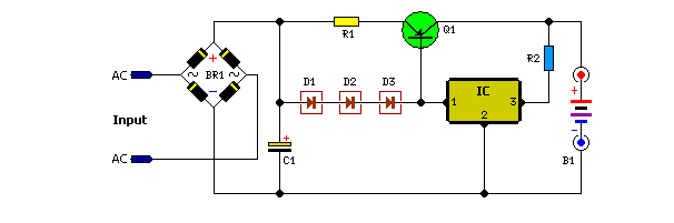
The automatic fan controller circuit is designed to regulate fan operation based on temperature variations. It employs two comparators, typically operational amplifiers configured as comparators, which monitor the temperature through a temperature sensor, such as an LM135 or a thermistor. The circuit allows for individual adjustment of the triggering points for each comparator, enabling customization of the activation and deactivation thresholds for the fan.
In this configuration, the first comparator is set to activate the fan when the temperature exceeds a predetermined level, while the second comparator can be set to deactivate the fan when the temperature drops below a different threshold. This dual-threshold system ensures efficient cooling and prevents unnecessary fan operation, contributing to energy savings and extended component lifespan.
The LM135 can be used as a temperature sensor, providing a voltage output proportional to the temperature. The output of the LM135 is fed into the inverting and non-inverting inputs of the comparators. By adjusting the reference voltages applied to the non-inverting inputs, the triggering points can be finely tuned to meet specific cooling requirements.
The circuit may also include additional components such as resistors, capacitors, and possibly a relay or transistor to drive the fan. The relay or transistor acts as a switch that controls the power supplied to the fan based on the output of the comparators. This arrangement allows for a robust and efficient fan control system, suitable for various applications where temperature regulation is essential.
Overall, the automatic fan controller circuit offers an effective solution for managing fan speed and operation based on ambient temperature conditions, promoting optimal performance and energy efficiency.The automatic fan controller circuit shown in the schematic has 2 comparators with different triggering points that are independently adjustable. LM135 or.. 🔗 External reference
Related Circuits

The composite pipe circuit limits the bulb cold current of the circuit. When the input signal is weak, a composite pipe circuit protection circuit is utilized, as illustrated in Figure 1. The composite pipe circuit functions as a protective mechanism...
If the audio input is a microphone, it is expected to precede an amplifier to achieve an output power of approximately 8W. The amateur seeking to enhance a small transmitter, which is likely already constructed, can utilize this circuit,...
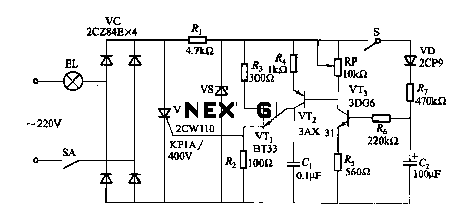
A fade-in fade-out light switch enables gradual adjustments in lamp brightness, allowing the light to turn on and off smoothly. When the switch SA is closed, the lamp brightness increases from dim to bright. Conversely, when the switch SA...
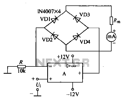
An operational amplifier, a diode bridge rectifier, and DC mA AC voltmeter tables are illustrated in the figure. The operational amplifier used is the LM324. The measured AC voltage is applied to the inverting terminal of the operational amplifier,...
The electronic fishing shrimp machine circuit consists of an astable oscillator, an inverter circuit, and a high-voltage output circuit, as depicted in Figure 20. The astable oscillator circuit includes a time-base integrated circuit (IC), resistors R3 and R4, a...
Unlike many units, this battery charger continuously charges at maximum current, tapering off only near full battery voltage. In this unit, the full load. This battery charger is designed to operate with a continuous charging mechanism, maintaining the maximum current...