
auto power off schematics
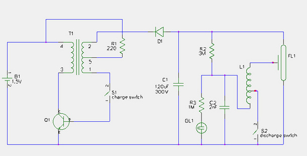
The described circuit functions as an automatic power switch for battery-operated devices, enhancing battery life by preventing unnecessary power drain. The core component, the p-n-p Darlington transistor (T1), is selected for its high current gain, which allows for efficient operation even with low input signals. The push-button switch (S1) serves as the user interface for initiating the circuit. When pressed, it activates T1, allowing current to flow from the 9 V battery to the load.
The timing mechanism is established through the combination of capacitor C1 and resistors R1 and R2. The values of these components dictate the timing characteristics of the circuit. Specifically, C1 charges through R3 when S1 is pressed, and the time constant defined by R1 and C1 determines how long T1 remains on. After the preset time elapses, R1 discharges C1, leading to the deactivation of T1 and cutting off power to the device. This design effectively conserves battery life by ensuring that power is only supplied when necessary.
The choice of components is critical to the circuit's performance. Resistor R3 is selected to limit the initial charging current to C1, thereby protecting S1 from excessive wear. The circuit's simplicity and reliance on passive components contribute to its reliability and ease of integration into various battery-operated devices. The absence of a polarity protection diode simplifies the design, as the Darlington transistor's specifications allow it to handle the input voltage without risk of damage.
Overall, this automatic power switch circuit represents an effective solution for extending the operational life of battery-powered devices, ensuring that they remain functional while minimizing the risk of battery depletion due to prolonged inactivity.We are surrounded by battery operated equipment of all kinds, and this array is growing still. Manufacturers and designers lean over backwards to make sure that their equipment draws a small current and can thus be operated by a battery. This has its flip side, too. because even if the equipment in question draws only a small current, when it is n ot switched off, the battery is flat after a few days or weeks. The circuit presented here can prevent this happening. It may be added to all kinds of equipment operating from a 9 V battery and switches this off automatically one minute after a preset time has elapsed. The peak switching current is 20 mA, which is more than enough for most applications. The switch is formed by a p-n-p darlington, T1, which is actuated by push-button switch S1. The very high amplification of the darlington enables it to be kept on fairly long with the aid of a relatively small-value capacitor, C1 (= 100 µF).
Resistor R3 limits the charging current of C1 to ensure a long life of S1. Resistors R1 and R2, in conjunction with C1, determine the switch-on time. When this time has elapsed, R1 ensures that T1 is switched off. Since the darlington can handle a UBE of 10 V, a polarity protection diode is not needed. 🔗 External reference
Related Circuits
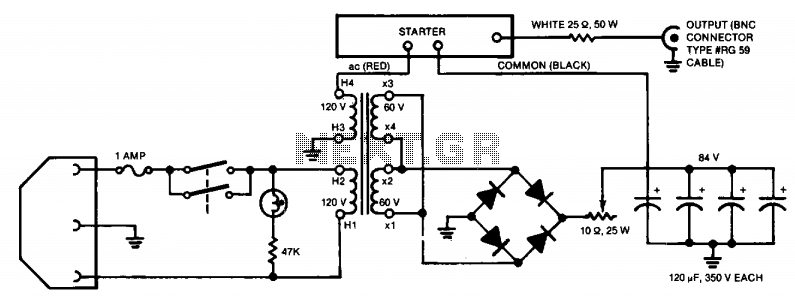
A dual-voltage circuit both initiates and sustains the arc. The lamps necessitate a starting voltage exceeding 1,000 volts. Once stable, the voltage across the lamp is approximately 20 volts. The power supply is divided into two primary sections. The...
The losses in a bridge rectifier can become significant when rectifying low voltages. The voltage drop across the bridge is approximately 1.5 V, which constitutes about 25% loss with an input voltage of 6V. This loss can be reduced...
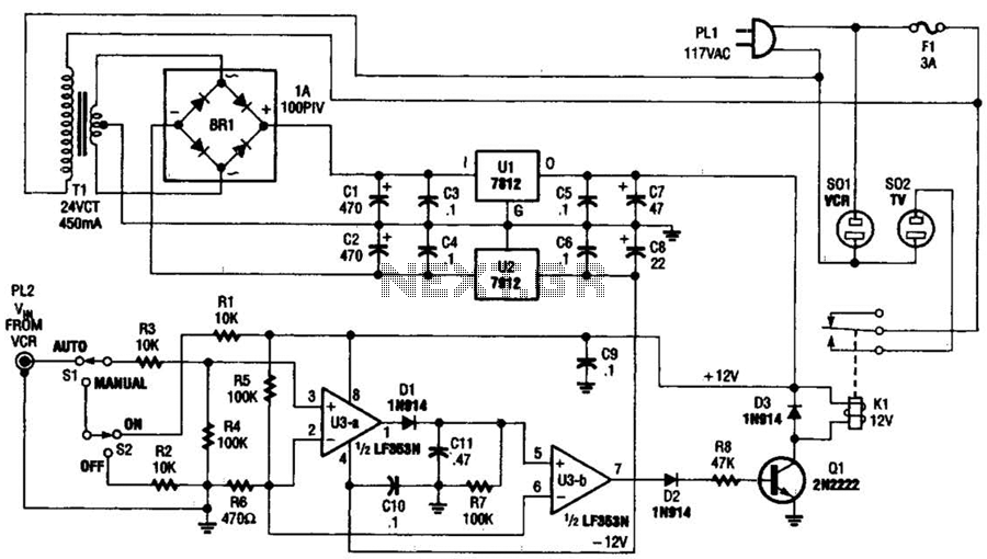
This circuit detects the video signal from the VCR. When the VCR is powered on, the video signal is amplified by U3A to drive Q1, which activates K1. This setup eliminates the need to manually turn on and off...
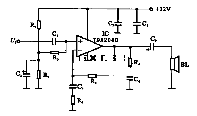
An integrated power amplifier TDA2040 is used in an OTL (Output Transformer-Less) power amplifier circuit, which operates with a +3V single supply as the working voltage. This circuit has a voltage gain of 30 dB (approximately 32 times magnification),...
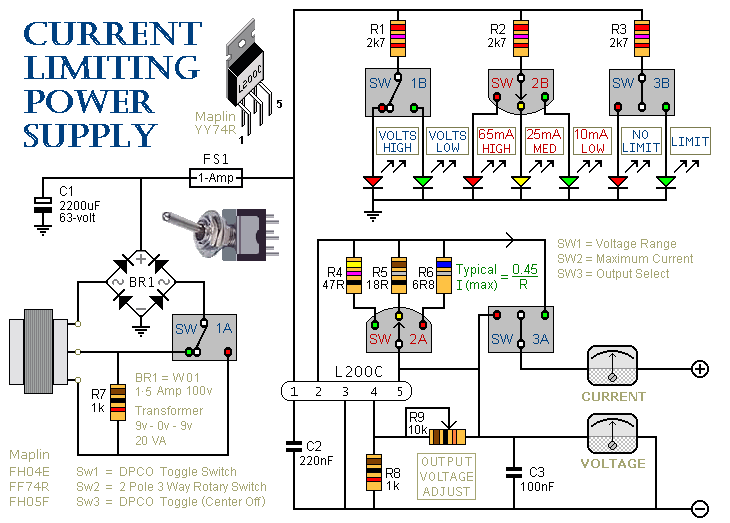
This is a 1-amp variable-voltage power supply unit (PSU) that can adjust the output voltage from approximately 3V to 24V. It includes a feature that allows for the limitation of the maximum output current, which is particularly useful when...
This document provides a step-by-step guide for modifying a disposable camera flash unit to serve as a power supply for a Geiger tube. The process involves removing the flash tube and trigger transformer from the circuit board by gently...