
Power MOSFET Bridge Rectifier
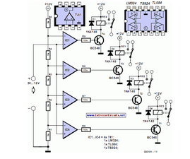
The synchronous rectifier circuit described employs a four-MOSFET configuration, which enhances efficiency by minimizing voltage drops during the rectification process. The control logic, implemented with a TL084 operational amplifier, is responsible for driving the MOSFETs based on the input AC voltage levels. The voltage dividers (R1, R4, R5, and R8) are designed to ensure that the MOSFETs are activated at the correct moments, preventing premature switching that could lead to increased losses. The use of high-precision resistors (1% or better) is crucial to maintain the stability and performance of the voltage sensing and control circuitry.
The internal diodes of the MOSFETs play a critical role during the startup phase of the circuit. They allow for initial conduction, enabling the rectifier to begin functioning even when no voltage is present. This characteristic is particularly beneficial for applications where rapid startup is essential. The selection of MOSFETs should consider their on-resistance, as lower resistance values will result in reduced conduction losses, thus improving overall efficiency.
In applications where the input voltage exceeds 6 V, adjusting the resistor values in the voltage dividers ensures that the control circuit operates effectively across a range of input voltages. This flexibility allows the synchronous rectifier to be used in various applications, from low-voltage power supplies to higher voltage systems, while maintaining optimal efficiency and performance.The losses in a bridge rectifier can easily become significant when low voltages are being rectified. The voltage drop across the bridge is a good 1. 5 V, which is a hefty 25% with an input voltage of 6V. The loss can be reduced by around 50% by using Schottky diodes, but it would naturally be even nicer to reduce it to practically zero.
That`s pos sible with a synchronous rectifier. What that means is using an active switching system instead of a passive` bridge rectifier. The principle is simple: whenever the instantaneous value of the input AC voltage is greater than the rectified output voltage, a MOSFET is switched on to allow current to flow from the input to the output. As we want to have a full-wave rectifier, we need four FETs instead of four diodes, just as in a bridge rectifier.
R1 R4 form a voltage divider for the rectified voltage, and R5 R8 do the same for the AC input voltage. As soon as the input voltage is a bit higher than the rectified voltage, IC1d switches on MOSFET T3. Just as in a normal bridge rectifier, the MOSFET diagonally opposite T3 must also be switched on at the same time.
That`s taken care of by IC1b. The polarity of the AC voltage is reversed during the next half-wave, so IC1c and IC1a switch on T4 and T1, respectively. As you can see, the voltage dividers are not fully symmetrical. The input voltage is reduced slightly to cause a slight delay in switching on the FETs. That is better than switching them on too soon, which would increase the losses. Be sure to use 1% resistors for the dividers, or (if you can get them) even 0. 1% resistors. The control circuit around the TL084 is powered from the rectified voltage, so an auxiliary supply is not necessary.
Naturally, that raises the question of how that can work. At the beginning, there won`t be any voltage, so the rectifier won`t work and there never will be any voltage. Fortunately, we have a bit of luck here. Due to their internal structures, all FETs have internal diodes, which are shown in dashed outline here for clarity.
They allow the circuit to start up (with losses). There`s not much that has to be said about the choice of FETs it`s not critical. You can use whatever you can put your hands on, but bear in mind that the loss depends on the internal resistance. Nowadays, a value of 20 to 50 mW is quite common. Such FETs can handle currents on the order of 50 A. That sounds like a lot, but an average current of 5 A can easily result in peak currents of 50 A in the FETs.
The IRFZ48N (55 V @ 64 A, 16 mW) specified by the author is no longer made, but you might still be able to buy it, or you can use a different type. For instance, the IRF4905 can handle 55 V @ 74 A and has an internal resistance of 20 mR. At voltages above 6 V, it is recommended to increase the value of the 8. 2-kR resistors, for example to 15 kR for 9V or 22 kR for 12 V. 🔗 External reference
Related Circuits
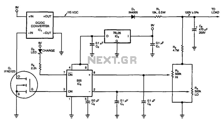
This circuit switches its DC/DC converter, IC1, off whenever the large filter capacitor, C6, has sufficient charge to power the load. This particular circuit uses a DC/DC converter that produces 115 Vdc from a 9 Vdc input; it can...
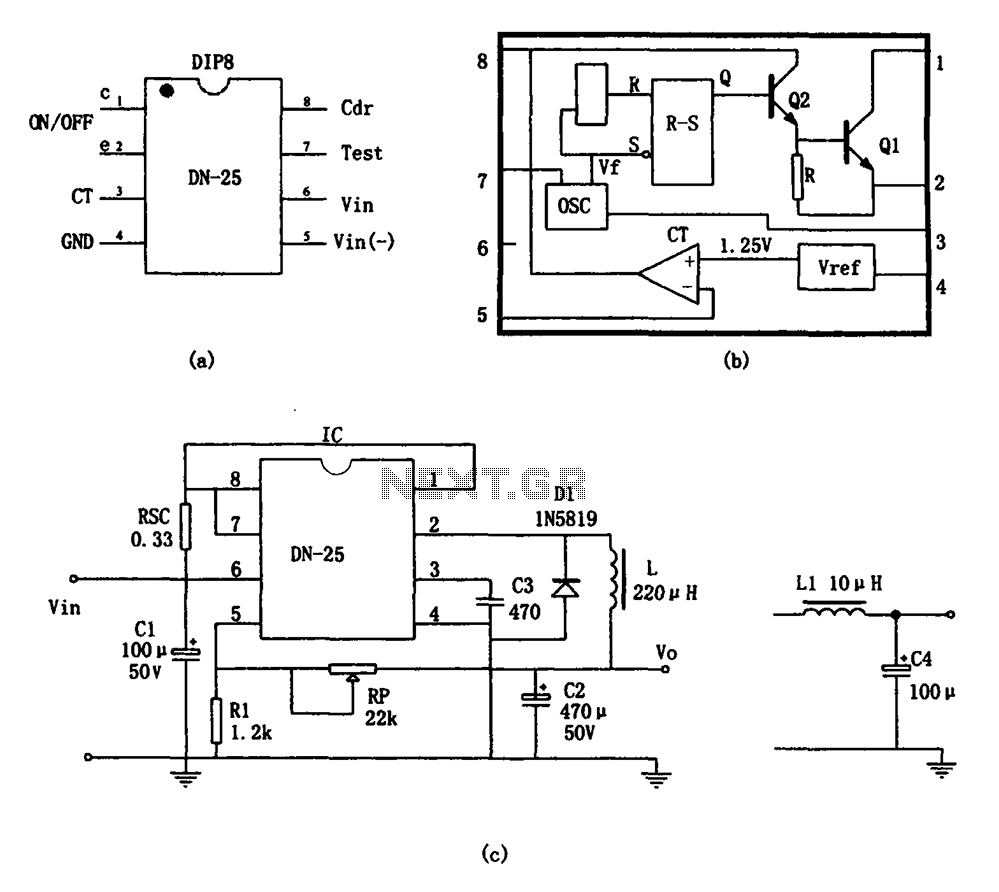
As shown in the figure, the DN-25 IC is a switching power supply. The DN-25 is a monolithic switching power supply device suitable for medium output current applications and a wide voltage range. Its main performance indicators include an...
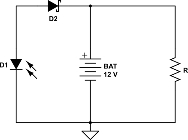
A 12V battery is charged using a solar panel. When the battery reaches 12V, the solar panel is disconnected from the battery, and the load is connected to the battery. The solar panel is reconnected to the battery when...
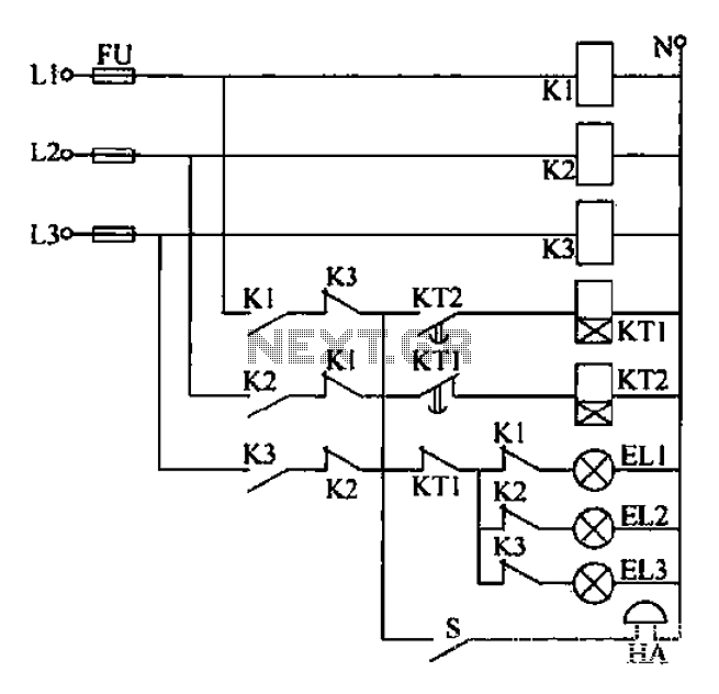
Any power supply and distribution sector should include phase sequence detection to ensure that the power supply phase sequence remains stable and unchanged. Additionally, any irreversible electromechanical product should also incorporate phase sequence detection to verify the phase sequence...
This circuit demonstrates that microprocessors, personal computers, and the latest ultra-accurate digital-to-analog converters (DACs) are excessive for the task of sequentially controlling four relays. The circuit utilizes a simple microcontroller or a basic timer IC to manage the operation of...
This is a replacement power source for 1.3V mercury cells or other small batteries. It has many uses and I use this circuit in my computer to power a front panel multi adapter which has a digital thermometer. This...
Warning: include(partials/cookie-banner.php): Failed to open stream: Permission denied in /var/www/html/nextgr/view-circuit.php on line 713
Warning: include(): Failed opening 'partials/cookie-banner.php' for inclusion (include_path='.:/usr/share/php') in /var/www/html/nextgr/view-circuit.php on line 713