
Camera Trip Circuit

The circuit employs a dual timer integrated circuit (U1), which is typically a 555 timer or a similar variant. The grounding of pin 2 serves as the trigger input for the timer, initiating the timing sequence. When pin 2 is grounded, it causes an internal flip-flop within U1 to switch states, resulting in pin 4 transitioning to a high state. This high state output is crucial as it determines the operational readiness of the timer.
The configuration of resistors (R7) and capacitors (C3) establishes the time constant for the timer circuit. The values of R7 and C3 can be selected to control the duration for which pin 4 remains low, effectively determining the minimum time interval between successive triggers. This feature is essential for preventing the camera from being triggered multiple times in rapid succession, thus conserving film and ensuring proper exposure.
The second output from the timer is utilized to create a half-second pulse. This pulse is directed to U4, which functions as a relay driver. The relay (Q1) is activated by this pulse, allowing it to close the circuit connected to K1, which ultimately triggers the camera shutter mechanism. The relay acts as an intermediary switch, capable of handling higher currents than the timer output, ensuring reliable operation of the camera.
Overall, this circuit showcases a practical application of timing mechanisms in electronic devices, providing a controlled method for activating a camera shutter while safeguarding against unnecessary film exposure. The careful selection of components and their configurations facilitates precise timing and reliable performance in triggering the camera. This circuit was used to trip a camera shutter. Grounding pin 2 of U1 makes pin 4 of U1 go high. This triggers both tim ers of dual timer Ul. One output holds reset (pin 4) of U1 low to keep U1 from accepting another trigger, depending on the time constant of R7 and C3. This prevents camera film waste. The other timer is used to generate a 1/2-second pulse to drive U4 and Ql, the relay driver. K1 triggers the camera.
Related Circuits
To avoid excess ripple output on a power supply feeding a heavy load, usually a large value capacitor is chosen following the rectifier. In this circuit, C1 is only a 470uF capacitor. The gyrator principle uses the effect that...

Personal Safes are revolutionary locking storage cases that open with just the touch of your finger. These products are designed as secure storage for medications, jewelry, weapons, documents, and other valuable or potentially harmful items. These utilize fingerprint recognition...
Power pulse circuit using LM350 and NE555. This circuit can be used to drive lamps, power LEDs, DC motors, etc. Adjust R5 for output amplitude and R1 for output power. The LM350 is an adjustable 3-terminal voltage regulator. The power...
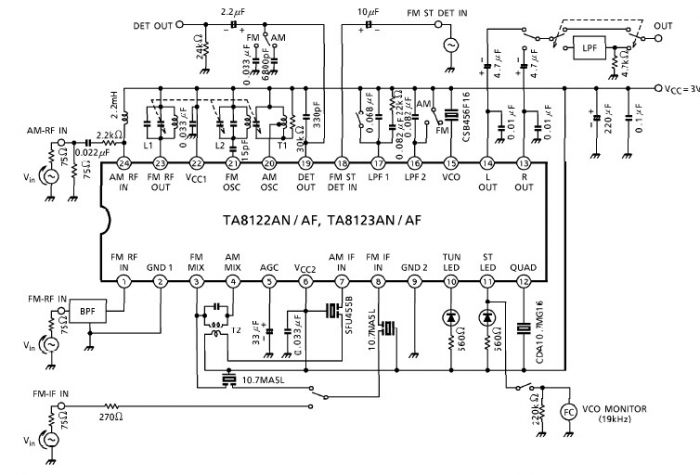
A simple low-power AM/FM radio receiver electronic project can be designed using the TA8122 integrated AM/FM receiver, manufactured by Toshiba Semiconductor. This radio receiver circuit is suitable for portable radio applications or other similar devices. The TA8122 radio receiver...
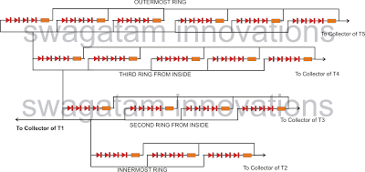
The following article outlines a sophisticated LED sequencing and diverging ring light that can serve as a tail brake light in vehicles. This circuit concept was proposed by a dedicated reader, Mr. Bobby. The design aims to create a...
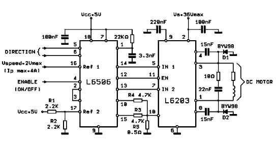
The L620x is a monolithic full bridge switching motor driver implemented using the new Multipower-BCD technology. This technology enables the integration of multiple isolated DMOS power transistors along with mixed CMOS/bipolar control circuits. The L620x series includes various versions:...