
2 Terminal Test Oscillator
The described circuit serves as a versatile tool for measuring inductance, operating at various frequencies with high reliability. The primary components include two FETs configured to create an oscillator that can be tuned to the desired frequency using a parallel LC circuit. The selection of FETs is crucial for achieving the desired frequency range; thus, using high-frequency components like the J310 is recommended for applications requiring measurements beyond 30MHz. The circuit's design allows for minimal complexity while ensuring accurate measurements, making it an ideal choice for amateur constructors and hobbyists. The ability to test coils in situ, particularly in practical applications, enhances its utility, allowing users to evaluate performance without requiring disassembly or complex setups. The circuit can also be adapted for other measurement tasks, demonstrating its multifunctional nature. Overall, this system provides an effective and economical solution for inductance measurement, catering to the needs of hobbyists and professionals alike.Anyone who is interested in home construction will at some time or other have the need to measure the inductance of small coils. This can be a difficult problem, as commercially made equipment of sufficient accuracy is often far too expensive for occasional use in an amateur workshop.
The simple LCR bridges that are affordable generally only Work at audio frequency and are notoriously inaccurate on their Low inductance ranges. The result of this is that coil construction is often so hit-and-miss that for many applications the home constructor has to use expensive ready made coils, which could have been wound at home from materials costing a few pence if test facilities had been available. The method of measurement described here is a inexpensive solution to the problem that I have been using for over 40 years.
It uses the coil under test in parallel with a known 1% capacitor to form the tuned circuit for a 2-terminal test oscillator. After making allowance for circuit strays, the total circuit capacity and the oscillating frequency can be entered in the standard resonant circuit formula to calculate the inductance.
of the coil accurately enough for all normal purposes. Using this method has the advantages that a) coils can be tested in a practical circuit at the operating frequency and b) measurements are just as easy to make on toroids and sealed coils such as IF transformers as they are on open coils. An additional bonus is that the circuit can be used for a variety of other purposes such as a signal generator, a dip meter or to measure small capacitors.
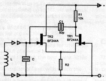
Fig. la shows the basic circuit of an FET source coupled 2terminal oscillator, which is the semiconductor version of a valve circuit that was popular in the 1950s. This circuit, which was derived from an early radar pulse generator called a cathode-coupled multivibrator, forms a very active tuneable oscillator that can be made to work reliably from Low audio frequencies up to the VHF and UHF ranges.
The great advantage of this circuit, and the thing that makes it so useful as a test oscillator, is that it doesn`t need any sort of capacitive tap, inductive tap, or feedback winding to make it work. Simply connect a parallel tuned circuit across the two test terminals, apply power, and away it goes.
The only criteria are that the tuned circuit has a realistic LC ratio (a minimum of 1-2 pF per metre of operating wavelength is a good rule of thumb for the capacitor value), and is made from good quality components. Operation of the circuit itself is quite straightforward. TR2 in Fig. la is an FET source follower that is directly coupled to the common gate FET amplifier TR1 by way of their shared load resistor R2.
C1 provides a positive feedback path from the drain of TR1 to the gate of TR2 and this maintains oscillation at the resonant frequency of LC so long as the loop gain of TR1, TR2 is enough to overcome circuit losses. Fig lb is the same circuit rearranged to allow R1 to be increased in value from 10k to 2M2. This reduces damping of the tuned circuit which in turn extends the frequency range and gives more consistent operation with Iow-Q coils.
The improvement given by this simple change is quite significant, as with cheap general purpose 2N3819 FETs my original circuit oscillated up to 15MHz whereas the modified one worked to over 25MHz. The BF244A FETs suggested in the parts list are suitable to 30MHz or more, but operation at higher frequencies than this calls for VHF type FETs.
Out of several readily available types that I tested, the best were J310s (listed as VHF/UHF oscillators/amplifiers) with which the oscillator worked from a few hundred Hz (with a homemade ferrite pot-cored coil plus lpF) up to 60MHz with a small hairpin loop tuned by 25pF (the stray capacity of my test oscillator). Fig. 2 gives the practical version of the tester, where TR1 and TR2 are connected as in the oscillator circuit of Fig lb
🔗 External reference
Related Circuits
This LCD terminal provides two modes of operation by selecting jumper J1. When J1 is open, the terminal operates as a normal ASCII display terminal; when J1 is closed, the terminal displays the input serial data in hexadecimal format....
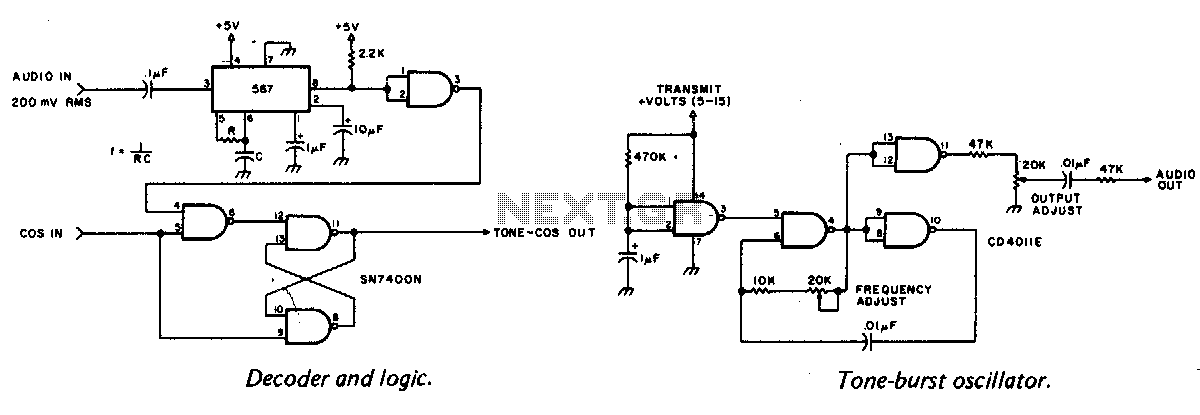
A tone burst sent at the beginning of each transmission is decoded at the receiver by a phase-locked loop (PLL), resulting in an output from pin 3 of a logic gate that activates a carrier-operated switch (COS). In this circuit,...
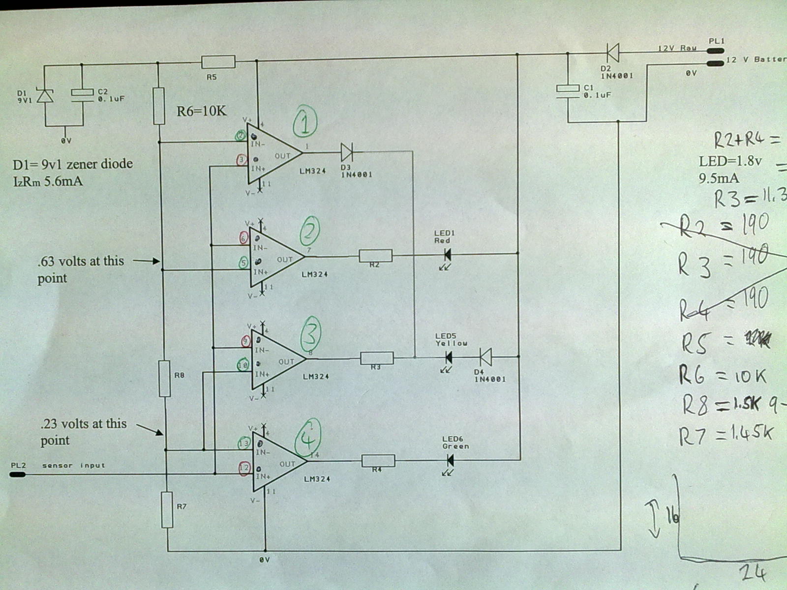
A 12V power supply is connected to the positive terminal, allowing current to flow through a protection diode and a capacitor that smooths the voltage. A zener resistor (R5) limits the current to the zener diode, which regulates the...
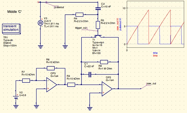
A design for a digitally controlled analog oscillator is being developed. The control voltage is generated by a microcontroller (Arduino) and is utilized through two operational amplifiers, along with a resistor and capacitor network that forms an integrator circuit....
A simple and easy telephone line tester circuit that can be used for testing telephone lines. The telephone line tester circuit is designed to verify the functionality and integrity of telephone lines. It typically comprises a few essential components, including...
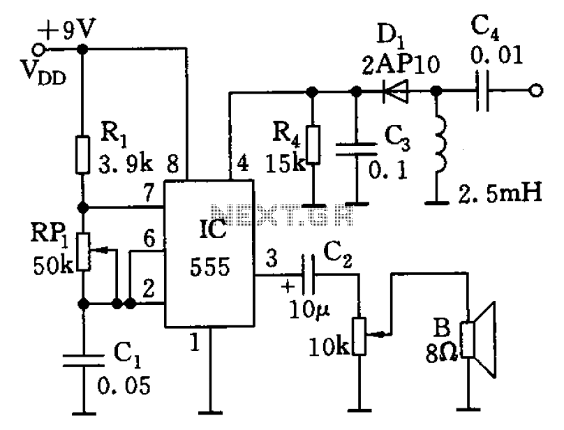
The circuit features a 555 timer along with resistors R1, RP1, and capacitor C1, functioning as a controllable audio oscillator. The frequency of the oscillator is determined by the formula f = 1.44 / ((R1 + 2 * RP1)...