
Automated instrumentation wiring using interference filters
Automated instrumentation wiring employing interference filters is essential for minimizing the effects of electromagnetic interference (EMI) on inverter systems. Inverters, which convert direct current (DC) to alternating current (AC), can generate significant electromagnetic emissions, especially when operating under high load conditions. These emissions can distort the readings of sensitive instrumentation and lead to inaccuracies in measurements.
To mitigate these issues, proper installation practices must be followed. It is recommended that the distance from the meter to the inverter should not exceed 200mm, and the meter should not be positioned on the same layer as the shielding box. This configuration helps reduce the coupling of electromagnetic fields into the measurement circuit, thereby minimizing potential errors.
Grounding is another critical aspect of the installation. The instrument ground terminal must be securely connected to ensure a stable reference point for the measurements and to prevent ground loops, which can introduce additional noise into the system.
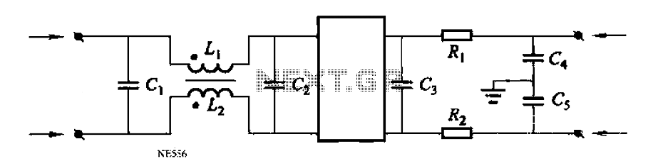
The filtering process for the instrument's input cable and power cord is vital for suppressing high-frequency noise. The selected capacitor (0.1μF, 250V) serves to block high-frequency noise while allowing the desired signals to pass through. The inductance of 10mH, with a DC resistance of less than 5Ω, aids in further filtering out unwanted electromagnetic interference. The resistor (100Ω, 1/2W) is included in the design to provide a damping effect, which can help stabilize the circuit and improve the overall response time of the instrumentation.
In summary, careful consideration of the installation parameters, grounding practices, and component selection is essential for ensuring accurate and reliable operation of automated instrumentation in the presence of high amplitude electromagnetic waves. Proper implementation of these measures will enhance the performance of the system and reduce measurement errors significantly. Automated instrumentation wiring using interference filters for the inverter is not as harmonic processing and the like, when the work will be radiated field strength of strong , high amplitude electromagnetic wave, if the meter is installed in the automation from its lack of 200mm, placed in not the same layer as the shielding box, the meter may yield additional error birth. This time should be the instrument ground terminal properly connected, then the instrument input cable and power cord for the filtering process, as shown in FIG.
Now the capacitor C selection 0. lFtF, 250V; inductance L take lOmH, DC resistance of less than 5Q; resistor R to select 100n, 1/2W.
Related Circuits
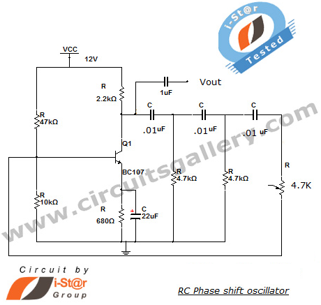
This section introduces a transistor oscillator circuit known as the RC Phase Shift Oscillator. An oscillator is an electronic circuit that functions as a sine wave generator, requiring only a DC power supply. It is commonly used in variable...
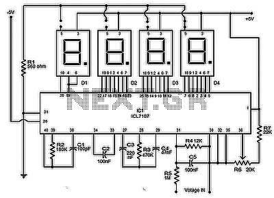
The circuit presented is a highly useful and accurate digital voltmeter featuring an LED display, utilizing the ICL7107 integrated circuit from Intersil. The ICL7107 is a high-performance, low-power, 3.5-digit analog-to-digital converter (ADC). This IC incorporates internal circuitry for seven-segment...
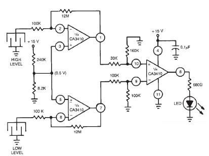
This liquid level sensor electronic circuit diagram utilizes a common CA3410 operational amplifier integrated circuit (IC). The sensor employs two plate sensors (or probes), one designated for detecting high liquid levels and the other for low liquid levels. If...
This circuit is a signal line so that you reinforce with a small speaker can control. The LM 386 is a number of versions available. LM 386N-1 can provide a power of 325 mW, the LM-386N 2500 mW, the...
This article is intended for complete beginners with servo motors. It provides an overview of the basic theory behind servo motors and offers detailed instructions on how to utilize them with AVR microcontrollers such as the ATmega32. Servo motors are...
One of the most effective communication methods to be implemented in a digital system is the use of the RS232 serial line. The microcontroller 89S51 is equipped with a UART, allowing it to perform serial communication at RS232 levels...