
Servo Motor Control by Using AVR ATmega32 Microcontroller

Servo motors are electromechanical devices that convert electrical energy into precise angular motion. They are commonly used in robotics, automation, and control systems due to their ability to achieve accurate positioning. The fundamental components of a servo motor include a DC motor, a potentiometer, a control circuit, and a gearbox, which together enable the motor to achieve a specific angle based on input signals.
When interfacing a servo motor with an AVR microcontroller like the ATmega32, it is essential to understand the control signal requirements. Servo motors typically accept a PWM (Pulse Width Modulation) signal, where the width of the pulse determines the angle of rotation. For instance, a pulse width of 1.5 milliseconds usually corresponds to the neutral position (0 degrees), while pulse widths of 1 millisecond and 2 milliseconds correspond to the extreme positions (e.g., -90 degrees and +90 degrees, respectively).
To effectively control a servo motor using an ATmega32, the following steps are generally involved:
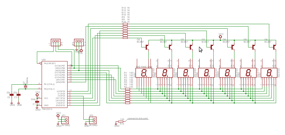
1. **Circuit Design**: A basic circuit includes the ATmega32 microcontroller connected to the servo motor. The control pin of the servo is connected to one of the PWM-capable pins of the microcontroller. Additionally, power supply connections must be established, ensuring that the servo receives the appropriate voltage and current.
2. **Programming the Microcontroller**: The firmware for the ATmega32 must be developed to generate the PWM signal. This typically involves configuring the timer registers to produce the correct frequency and pulse width. The microcontroller can be programmed using C or assembly language, with libraries available to simplify the PWM generation process.
3. **Testing and Calibration**: After the circuit is assembled and the program is uploaded to the microcontroller, it is important to test the setup. Calibration may be necessary to ensure that the servo responds accurately to the PWM signals. This can be achieved by adjusting the pulse widths in the code and observing the servo's response.
4. **Application Development**: Once the basic control is established, additional functionalities can be implemented. This may include integrating sensors for feedback, creating user interfaces for manual control, or developing algorithms for automated tasks.
By following these guidelines, beginners can successfully work with servo motors and AVR microcontrollers, opening the door to more complex projects in robotics and automation.This article is for complete beginners with servo motors. It teaches you the servo motor basic theory and gives detailed steps to use them with AVR Microcontrollers like ATmega32.. 🔗 External reference
Related Circuits
The project utilizes a 10 x 20 grid of RGB LEDs controlled by the myRIO. It is operated through a web interface on any device that supports WebSockets. Originally, the system was built using an Arduino, but the creator...
A NOS lathe is available, but it lacks any historical information. It appears to be purpose-built, and it is important to note that there is no available technical support for this equipment. The absence of historical context for the NOS...
In the production of LCD projectors, the primary factor threatening the lifespan of the LCD screen is the temperature generated by halogen lamps. The multi-function controller designed by this circuit is highly effective for protecting liquid crystal projectors. The...
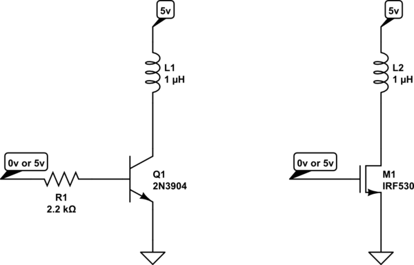
The project involves using an MC25060V2 fan, which needs to be controlled through software for on and off switching without utilizing PWM or complex methods. The proposed solution involves using either an NPN BJT or an N-channel MOSFET on...
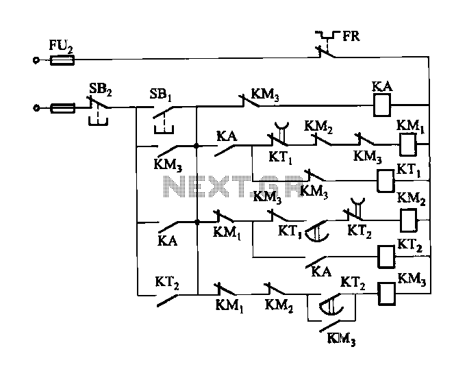
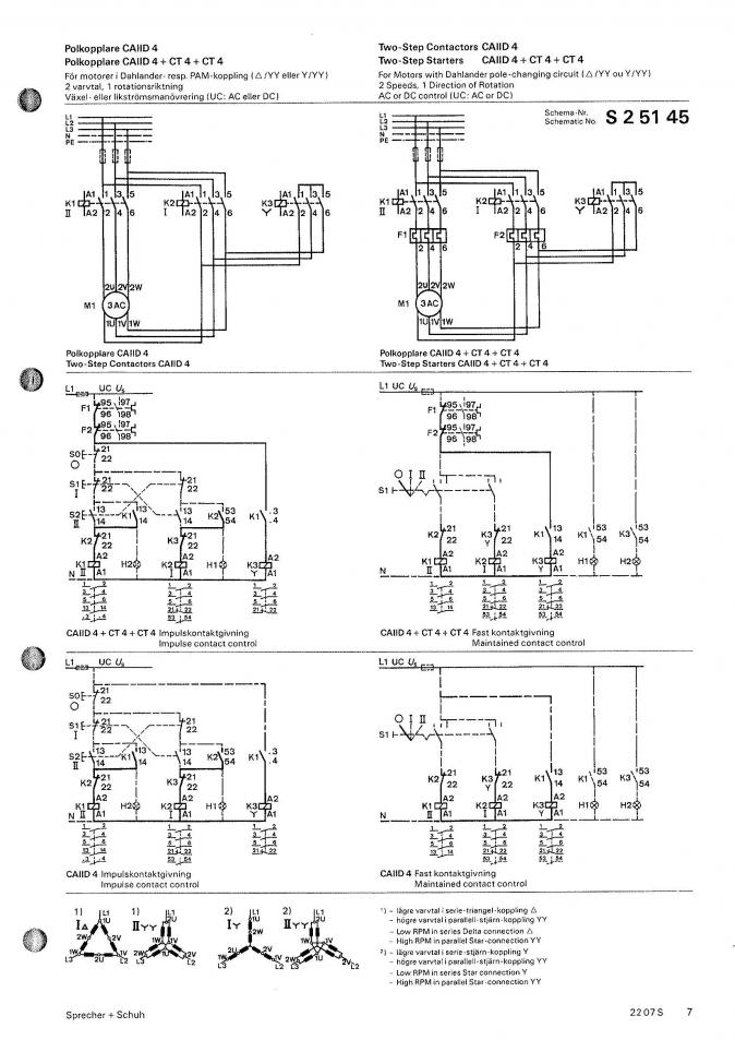
Figure 3-118 illustrates an automatic acceleration control circuit. This circuit employs a male contactor time relay, enabling the motor to start automatically at a low speed before transitioning to high-speed operation. The automatic acceleration control circuit depicted in Figure 3-118...
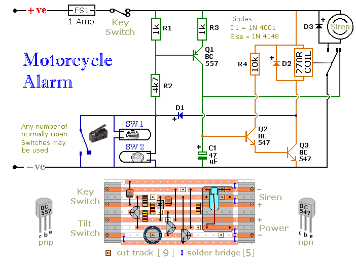
Any number of normally open switches may be used. Fit the mercury switches so that they close when the steering is moved or when the bike is lifted off its side-stand or pushed forward off its centre-stand. Use micro-switches...