
Automatic AC voltage regulator circuit TXD1742 continuous adjustment
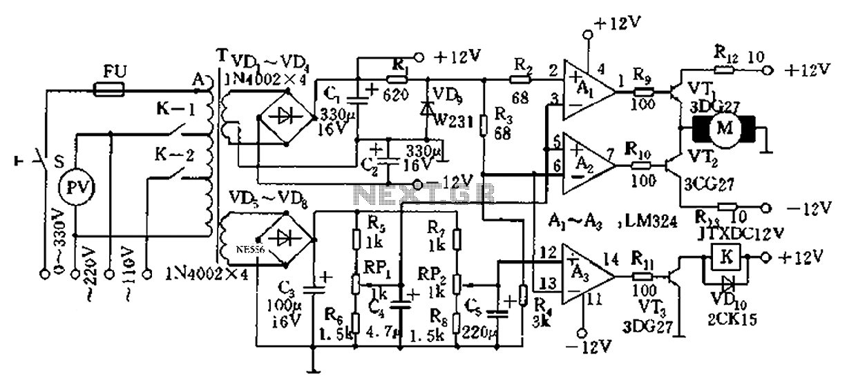
The TXD1742 is an automatic AC voltage regulator circuit designed to provide continuous voltage adjustment, ensuring stable output voltage in varying load conditions. This circuit is particularly useful in applications where voltage fluctuations can adversely affect the performance of electrical devices.
The core of the TXD1742 circuit typically includes a transformer, a rectifier, a voltage regulator IC, and various passive components such as resistors and capacitors. The transformer steps down the high AC voltage to a lower AC voltage suitable for regulation. The rectifier converts the AC voltage to pulsating DC, which is then smoothed by a filter capacitor to provide a stable DC voltage.
The voltage regulator IC is the heart of the circuit, responsible for maintaining a constant output voltage. It continuously monitors the output voltage and adjusts the duty cycle of the control signal to the power switch, which could be a transistor or a thyristor, to regulate the output voltage. The continuous adjustment feature allows for fine-tuning of the output voltage, accommodating different load requirements and ensuring optimal performance.
Additional components, such as zener diodes and operational amplifiers, may be included in the circuit design to enhance voltage regulation accuracy and improve transient response. Feedback loops are often employed to compare the output voltage with a reference voltage, allowing for real-time adjustments to maintain the desired output level.
Overall, the TXD1742 automatic AC voltage regulator circuit is an effective solution for applications requiring reliable voltage regulation, protecting sensitive electronic equipment from the adverse effects of voltage variations. Automatic AC voltage regulator circuit TXD1742 continuous adjustment
Related Circuits
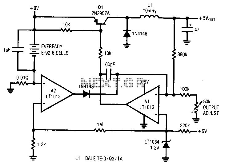
A simple battery-powered switching regulator provides 5 V output from a 9-V source with 80% efficiency and a 50 mA output capability. When Q1 is activated, its collector voltage increases, allowing current to flow through the inductor. This causes...
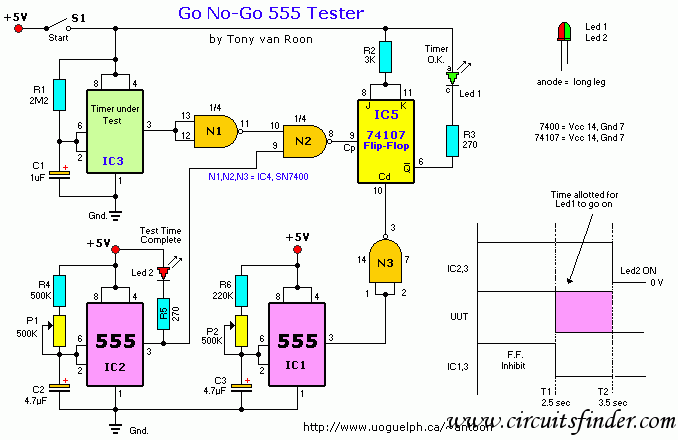
This circuit illustrates a Go-No/Go Tester Circuit utilizing a 555 Timer IC. Features include a more advanced unit with a precise timed testing procedure. The Go-No/Go Tester Circuit is designed to evaluate components or assemblies by providing a simple pass/fail...
FIG. 284 illustrates a practical emergency power lighting system that activates automatically in the event of a sudden power outage. The fluorescent lights serve as emergency lighting. If the primary illumination lamp is turned off due to a power...
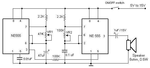
The primary components of this doorbell circuit include two NE555 timer integrated circuits (ICs). When the switch S1 is pressed momentarily, the loudspeaker emits a bell tone for the duration determined by the time period of the monostable multivibrator...
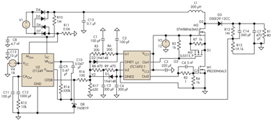
Adding a discharge path to the upper MOSFET of a cascode circuit significantly reduces the unavoidable Miller effect, thereby enhancing the Power Factor Correction (PFC) performance of a power supply's front end. In a cascode configuration, the upper MOSFET is...
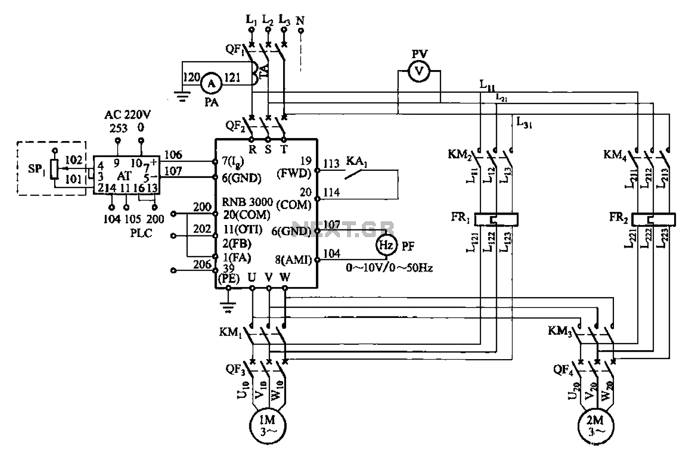
A control circuit for two motors, specifically for frequency control in a constant pressure water supply system, is illustrated in Figure 5-23. The circuit includes fault output terminals labeled 1 and 2, analog feedback current input terminals labeled 6...
Warning: include(partials/cookie-banner.php): Failed to open stream: Permission denied in /var/www/html/nextgr/view-circuit.php on line 713
Warning: include(): Failed opening 'partials/cookie-banner.php' for inclusion (include_path='.:/usr/share/php') in /var/www/html/nextgr/view-circuit.php on line 713