
A control two water supply frequency control circuit a
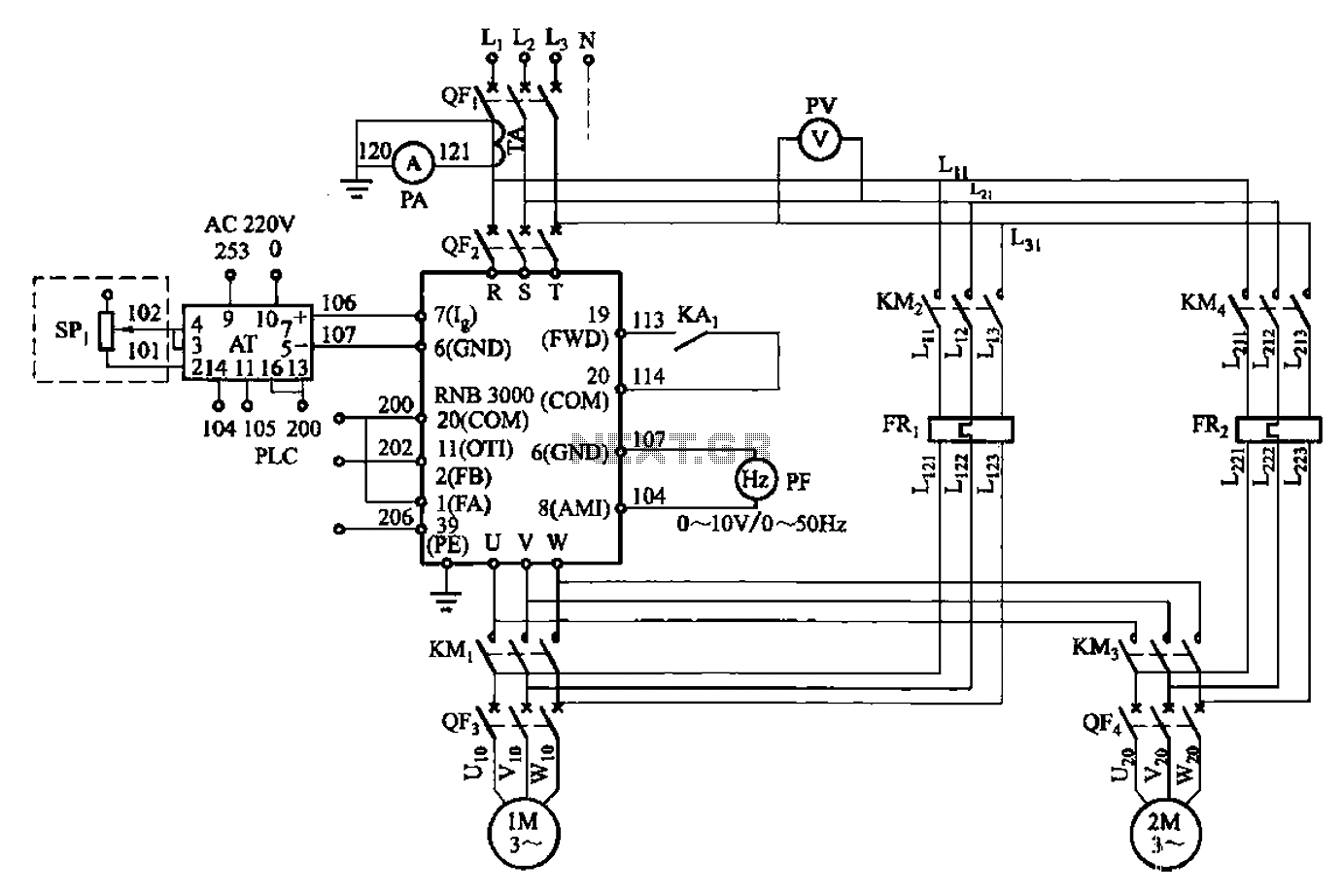
The described circuit operates as a frequency control mechanism for two motors that regulate the pressure of water in a supply system. The primary function of this circuit is to maintain a constant pressure by adjusting the motor speeds based on feedback received from various sensors.
The fault output terminals (1 and 2) are crucial for monitoring the operational status of the motors. If an anomaly is detected, these terminals will relay fault signals to a monitoring system, allowing for timely maintenance or intervention.
The analog feedback current input terminals (6 and 7) receive signals from current sensors that monitor the actual motor performance. This feedback is essential for the control system to make real-time adjustments to the motor speeds, ensuring that the desired pressure levels are consistently achieved.
Analog output terminals (6 and 8) are used to provide data to other components of the system, such as a controller or display unit. This data can include information on current motor speeds or pressure levels, allowing operators to have a clear view of the system's performance.
The forward run terminals (19 and 20) are responsible for initiating the operation of the motors in a forward direction. These terminals are typically connected to a control switch or relay that activates the motors when water supply is required.
Programmable digital output terminals (11 and 20) allow for customization of the control circuit’s functions. These outputs can be programmed to perform specific tasks, such as activating alarms or controlling additional components based on the operational status of the motors.
Overall, this control circuit is integral to maintaining efficient operation in a constant pressure water supply system, ensuring that the motors function optimally while providing critical feedback and control capabilities.A control two (namely a frequency control two motors) Frequency constant pressure water supply control circuit shown in Figure 5-23. Figure, 1,2 fault output terminal; 6,7 anal og feedback current input terminals; 6,8 is the analog output of the sub; 19, 20 to run forward terminal; 11, 20 programmable digital output terminal.
Related Circuits
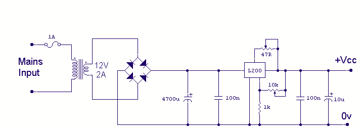
Using the versatile L200 voltage regulator, this power supply has independent voltage and current limits. The mains transformer has a 12-volt, 2 amp rated secondary, the primary winding should equal the electricity supply in your country, which is 240V...
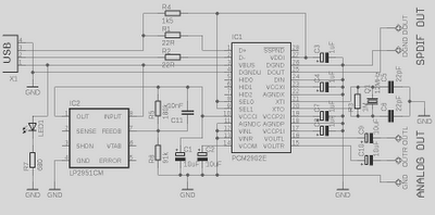
This is a high-quality preamplifier circuit with a built-in USB DAC designed for the Leachamp power amplifier. The schematic is derived from the PCM2902 datasheet. The circuit includes a DAC and ADC, SPDIF output and input, and an HID...
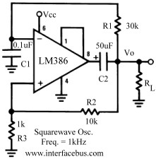
Several operational amplifier circuits are presented here, configured as square wave oscillators. A square wave is a periodic pulse train with a 50 percent duty cycle. The operational amplifier functions as a high-gain amplifier, and oscillation is achieved with...
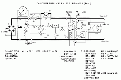
This power supply unit (PSU) has been designed for high-current ham radio transceivers, providing approximately 20 Amps at 13.8V. It features a secondary output capable of handling currents from 15 mA up to a maximum of 20A. The unit...
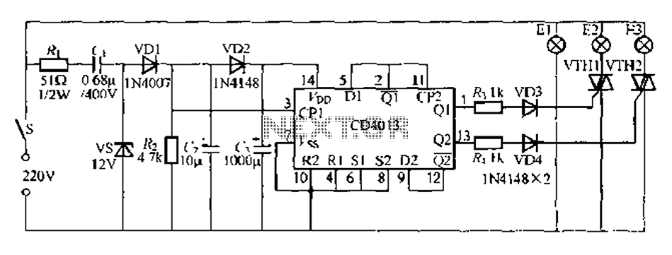
Figure 296 illustrates a control circuit that utilizes a switch (S) to manage three lamps (E1, E2, and E3) in a lighting system, suitable for controlling a chandelier in a living room. When the switch is off, all lights...
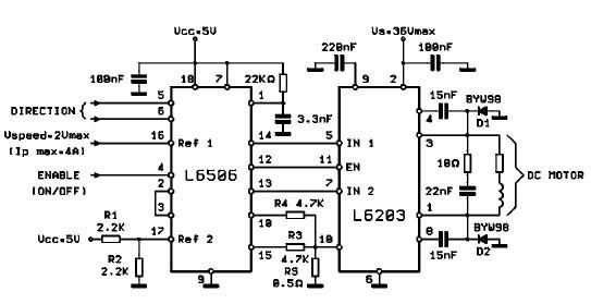
The L620x is a monolithic full bridge switching motor driver implemented using the new Multipower-BCD technology. This technology enables the integration of multiple isolated DMOS power transistors along with mixed CMOS/bipolar control circuits. The L620x series includes various versions:...
Warning: include(partials/cookie-banner.php): Failed to open stream: Permission denied in /var/www/html/nextgr/view-circuit.php on line 713
Warning: include(): Failed opening 'partials/cookie-banner.php' for inclusion (include_path='.:/usr/share/php') in /var/www/html/nextgr/view-circuit.php on line 713