
Automatic delay the start of operation of the circuit
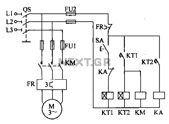
The described circuit operates on a systematic timing mechanism designed for automatic intermittent lubrication control. The power switch Qs serves as the primary control point, enabling the entire system once engaged. The manual switch SA provides a method for manual intervention, allowing the operator to control the motor's operation directly.
The time relay KT1 is crucial for establishing the initial delay before the motor starts. Upon activation, KT1 begins its timing cycle. The delay period is adjustable based on the requirements of the lubrication process, ensuring that the motor does not start until the specified time has elapsed.
Once KT1 completes its timing cycle, its closed contact energizes the contactor KM, which connects the motor to the power supply, initiating motor operation. At this point, KT2 also becomes energized, which is configured to introduce a second delay. The delayed closing contact of KT2 is set to engage after another specified period, which can be adjusted to control how long the motor runs before it is stopped.
The relay KA plays a vital role in the safety and control of the motor operation. When KT2's contact closes, KA is energized, which opens its break contact. This action interrupts the power supply to KT1, causing it to reset and open its contacts. As a result, both KT2 and KM are de-energized, halting the motor operation.
This circuit design allows for repeated cycles of operation, where the motor starts and stops based on the configured timing intervals. The continuous operation of KT1 while the manual switch SA is closed ensures that the timing mechanism remains active, allowing for consistent lubrication cycles. This setup is particularly beneficial in applications where intermittent lubrication is required to maintain machinery in optimal working condition, minimizing wear and extending the life of the equipment.
Overall, this motor boot delay intermittent operation circuit is an effective solution for automating lubrication processes, ensuring that machinery receives timely maintenance while preventing unnecessary operational downtime.After the line on the power switch, the motor does not start immediately, but to delay a specified period of time, the machine can be used for automatic intermittent lubricatio n control. Motor boot delay intermittent operation circuit shown 4-31 Fig. When closing the power switch Qs and manual switches SA, time relay KT1 is energized, the start time. After reaching KT1 setting time, which delay the closed contact is closed, the contactor KM is energized, the motor starter transport revolution.
At the same time KT2 also was electric pull, after - after a period of time, KT2 delay closing contact closure, the relay is energized KA, KA break contact disconnect, KT1 missing, and released its contacts open, KT2, KM. KA are de-energized, the motor is stopped, but the manual switch SA still in the closed state, so KTI entered timekeeping.
When arriving at the timing A, KT1 contact closes, the motor began to start running. After running the previous process said the same, tons of starter motor M is stopped, again and again.
Related Circuits
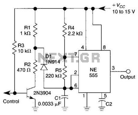
A 1-kHz gated oscillator with no long turn-on cycle is shown. R2, R3, and D1 preset the voltage on tuning capacitor C1 to a percentage of the supply voltage. The circuit described functions as a gated oscillator operating at a...
This is a simple circuit for automatic switchover between battery and USB port. This circuit uses a more general step-up converter architecture. The circuit designed for automatic switchover between a battery and a USB power source employs a step-up...
Instructions for supervising landscaping projects recommended by satellite relay protection and automatic safety devices. This includes information on the general table for three remote programs related to petrochemical engineering construction, electrical transmission, and the intelligent implementation of community weak...
.png)
Have you ever considered implementing your own home security alarm system? It is one of the simplest and most interesting circuits for electronics beginners. The new home security equipment utilizes a Light Dependent Resistor (LDR) to detect security breaches....
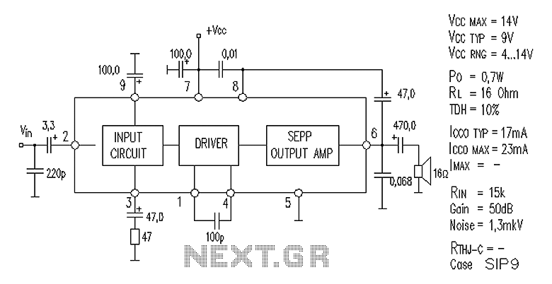
AN7112 power amplifier circuit diagram The AN7112 is a power amplifier designed for audio applications, capable of delivering high output power while maintaining high fidelity. The circuit diagram typically includes essential components such as transistors, resistors, capacitors, and a...
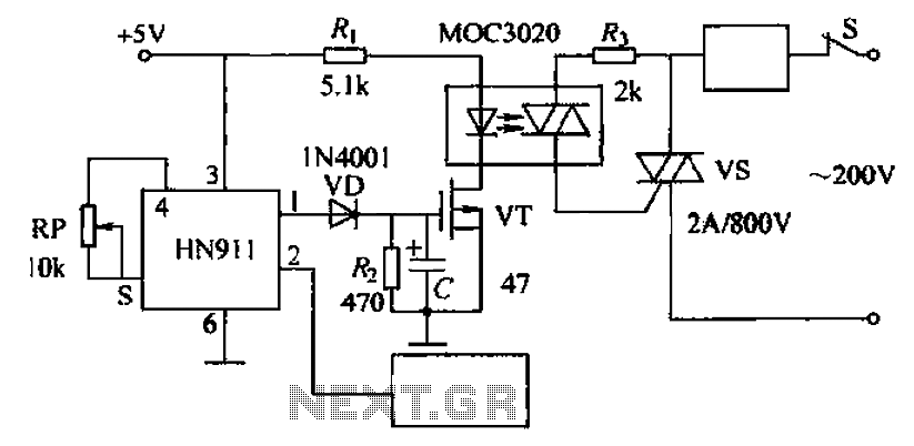
Automatic door control circuit diagram. It utilizes a pyroelectric infrared detection module, HN911, for human motion detection. A variable resistor (potentiometer) is used to adjust the delay time controlled by a transistor (VT). An optocoupler (MX: 3020) provides AC...
Warning: include(partials/cookie-banner.php): Failed to open stream: Permission denied in /var/www/html/nextgr/view-circuit.php on line 713
Warning: include(): Failed opening 'partials/cookie-banner.php' for inclusion (include_path='.:/usr/share/php') in /var/www/html/nextgr/view-circuit.php on line 713