
Precision Gated Oscillator Circuit
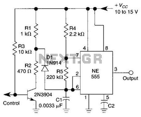
The circuit described functions as a gated oscillator operating at a frequency of 1 kHz. The primary components involved include resistors R2 and R3, diode D1, and tuning capacitor C1.
In this configuration, R2 and R3 are used to create a voltage divider that sets the reference voltage for the tuning capacitor C1. This configuration allows for precise control over the voltage applied to C1, which is crucial for determining the oscillation characteristics of the circuit. The diode D1 serves to prevent reverse current flow, ensuring that the voltage across C1 remains stable and within the desired range.
The oscillator operates without a long turn-on cycle, which implies that it can quickly reach its stable oscillation state upon activation. This characteristic is beneficial for applications requiring rapid response times. The gating mechanism likely involves a control signal that enables or disables the oscillator, allowing for flexibility in its operation.
Overall, this circuit is suitable for applications where a stable, low-frequency oscillation is required, and the ability to adjust the oscillation characteristics through the tuning capacitor is advantageous. The design emphasizes simplicity and efficiency, making it an effective solution for various electronic applications. A 1-kHz gated oscillator with no long turn-on cycle is show. R2, R3, and D1 preset the voltage on tuning capacitor CI to % of the supply voltage. 🔗 External reference
Related Circuits
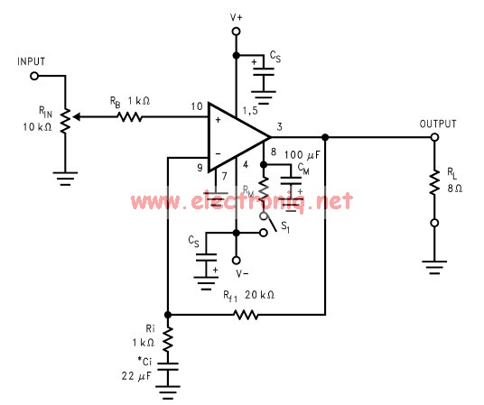
The LM3886 amplifier electronic circuit project is designed to deliver 68W of continuous average power into a 4-ohm load and 38W into an 8-ohm load with a total harmonic distortion plus noise (THD+N) of 0.1% across the frequency range...
The TX05C-R infrared surveillance alarm circuit is designed for monitoring walls, windows, doors, and various restricted areas. When an intrusion occurs, the alarm activates to enhance security. The circuit comprises a transmitter module, a receiver module, a time-base circuit,...
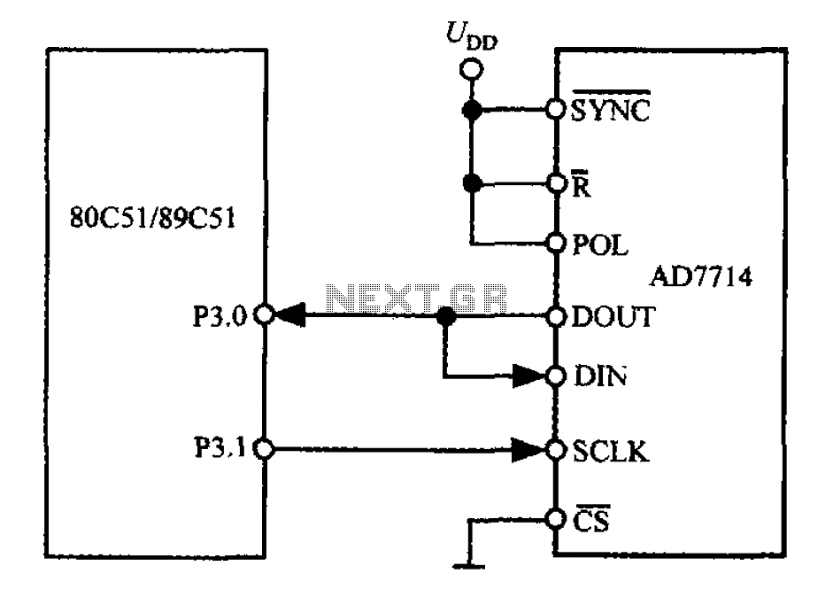
The 3-wire interface to the AD7714 can be utilized with various microcontrollers, including microcontrollers and microprocessors. This 3-wire serial interface is particularly suitable for isolation systems, allowing the use of optical couplers. The interface circuit between the AD7714 and...
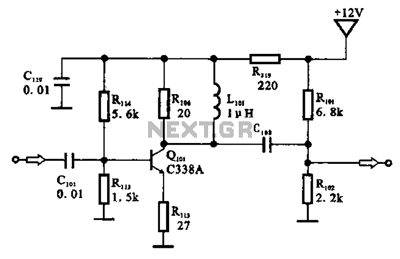
The amplifier circuit is designed as a pre-amplifier configuration. It utilizes transistor Q101 and other components such as inductor L101 and biasing elements. The transistor operates as a common emitter intermediate frequency (IF) amplifier. The IF signal is coupled...
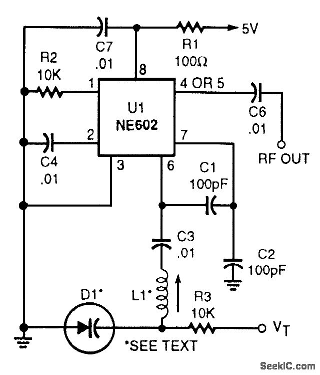
This voltage-tuned Clapp oscillator utilizes a varactor diode to determine its operating frequency. The diode used is an NTE614, and the inductor L1 has a value of approximately 7 microhenries. With this configuration, the oscillator can operate within a...
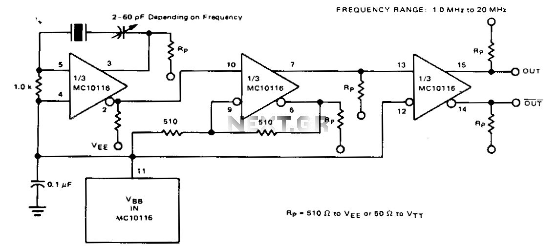
For frequencies below 20 MHz, a fundamental-frequency crystal can be utilized, eliminating the need for a resonant tank. At these lower frequencies, the typical MECL 10,000 propagation delay of 2 ns becomes negligible compared to the oscillation period, necessitating...
Warning: include(partials/cookie-banner.php): Failed to open stream: Permission denied in /var/www/html/nextgr/view-circuit.php on line 713
Warning: include(): Failed opening 'partials/cookie-banner.php' for inclusion (include_path='.:/usr/share/php') in /var/www/html/nextgr/view-circuit.php on line 713