
Home security alarm system circuit diagram
.png)
The home security alarm system described utilizes a basic yet effective circuit design that is ideal for beginners in electronics. The core component of this system is the LDR, which serves as a light-sensitive resistor. The circuit operates by continuously monitoring the light intensity of the LASER beam that is projected around the perimeter of the area to be secured.
The LASER torch emits a beam that is reflected by three strategically placed mirrors, creating a closed optical path. This arrangement ensures that the beam covers the entire area without gaps. Under normal conditions, the uninterrupted LASER beam keeps the LDR in a low-resistance state, resulting in a minimal voltage drop across it. This low voltage is insufficient to activate the transistor, which remains in the OFF state, preventing any alarm signal from being generated.
When an intruder crosses the LASER beam, the light incident on the LDR is obstructed, causing the resistance of the LDR to increase dramatically. This increase in resistance leads to a corresponding rise in voltage drop across the LDR. Once this voltage exceeds the threshold of approximately 0.6V, the NPN transistor (such as the BC547) switches to the ON state. This transition allows current to flow through the connected load, which could be an LED or a buzzer, effectively signaling a security breach.
This electronic circuit can be implemented on a breadboard for prototyping and testing purposes. The simplicity of the design makes it an excellent project for students, providing hands-on experience with fundamental concepts in electronics, including Ohm's law, transistor operation, and light sensing technologies. Additionally, the use of animation and simulation aids in understanding the functionality of the circuit, making it an engaging learning tool.Have you ever thought aboutimplementing your own home security alarm systems It`s one of the simplest and interesting circuits for electronic beginners. Our new home security equipment uses aLDR (Light Depended Resistor) to detect security problems. Theft attempt and other security threats can be controlled by using this simple circuit to improve yoursecurity systems. This is also best suited for school students for their high school science projects. To implement this alarm system for home, you have to provide an optical path (with LASER beams) around your home. The LASER path is made possible with one LASER torch and 3 mirror arrangements which encloses the whole area.
Please refer the project arrangement section below to make this optical (light) path. We have explained about home security system in detail with animation/ simulation. Thus the voltage drop across the LDR is also low [V=IR (Ohm`s law)] which is insufficient to turn ON the transistor, so the transistor remains in OFF state. When a person (eg: thief) makes a block to the continuous flow of LASER beam, then the light falling on the LDR gets blocked.
Thus its resistance increases to a high value in the order of M © range (According to Ohm`s law V=IR). While resistance increases the voltage drop also increases, when this voltage drop exceeds the cut in voltage of the silicon NPN transistor (0.
6V; BC547), it will turn ON. To realize the concept we are providing animation/ simulation of home security alarm circuit below. For animated demonstration, LED is used instead of buzzer. 🔗 External reference
Related Circuits

A typical specification can range from a low of 36V to a high of 72V, with a nominal value of 48V. In some designs, transients exceeding 100V must be considered. Most of these designs will require input to output...
The resistors were not measured precisely, and given their ±5% tolerance, along with a Vref range of 1.2 to 1.3 volts, it is possible to exceed 6 volts in certain scenarios. A discussion arose regarding the effectiveness of these...

This circuit is not visually appealing nor easy to implement, requiring considerable effort. The stepper motor consists of two coils, necessitating the use of two LMD18245 chips to manage the current flow through these coils. It is noteworthy that...
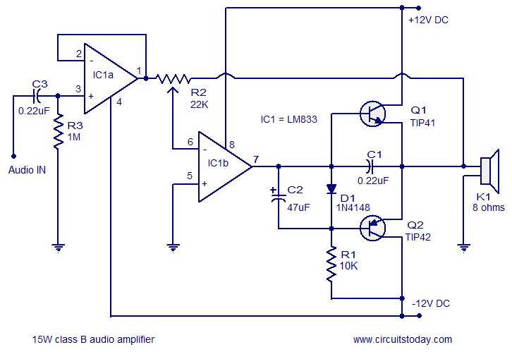
A 15 Watts Class B audio amplifier circuit is designed using a dual op-amp LM833. The schematic diagram is provided, and a potentiometer allows for volume control. The 15 Watts Class B audio amplifier circuit utilizes the LM833 dual operational...

This circuit is designed to connect stereo outputs from four different sources or channels as inputs, allowing only one of them to be selected and connected to the output at any given time. When the power supply is turned...

The following image illustrates the electrical wiring connection diagram for the Honda Motorcycle CB750F. It details the connections between various Honda components, including the right turn signal indicator light, oil pressure warning light, neutral indicator, high beam indicator, turn...
Warning: include(partials/cookie-banner.php): Failed to open stream: Permission denied in /var/www/html/nextgr/view-circuit.php on line 713
Warning: include(): Failed opening 'partials/cookie-banner.php' for inclusion (include_path='.:/usr/share/php') in /var/www/html/nextgr/view-circuit.php on line 713