
Make an Atom Synchronised Clock from a 1950s Slave Dial using Arduino
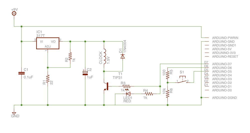
The circuit design for the slave dial mechanism incorporates several important elements to ensure reliable operation. The LM317 voltage regulator is essential for providing a stable voltage output to the coil, which is critical for the accurate advancement of the clock hands. By adjusting the output voltage to approximately 1.5 volts, the circuit can effectively drive the clock mechanism while avoiding the risks associated with overdriving or under-driving the coil.
The use of a TIP31 transistor as a switch allows for efficient control of the coil's power supply, and the placement of a diode across the coil serves to protect the circuit from back electromotive force (back-EMF), which can occur when the coil is de-energized. This back-EMF can potentially damage sensitive components if not properly managed.
In addition to the core functionality, the inclusion of an LED for debugging enhances the development process by providing visual feedback during programming and testing. The option to configure the system through an additional switch indicates a flexible design approach, allowing future enhancements or adjustments to be made easily, even if this feature was not ultimately utilized.
The choice of mounting the components on stripboard after prototyping on a breadboard demonstrates a systematic approach to circuit design. The use of DIYLC for layout design ensures that the final assembly is compact and organized, which is crucial for fitting within the constraints of the clock housing. The implementation of header sockets for the Arduino allows for easy removal and replacement, facilitating maintenance and upgrades.
Overall, this circuit design exemplifies careful consideration of both functionality and practicality, addressing the specific requirements of the slave dial mechanism while allowing for adaptability in future applications. The integration of various components and the thoughtful layout contribute to a robust and reliable electronic system.When I purchased the salve dial, it came with no instructions, packaging or other details. The only markings (other than five decades of grime) were those on the face (SMITH SECTRIC, ACELEC SYDNEY), and some markings on bracket holding the mechanism together (E. C. S. 205/19 MADE IN ENGLAND). There were markings on the coil, but they were too faint to read. In order to drive the mechanism, I needed to know how much voltage had to be applied to the coil to reliably advance the hands, for how long, and how many seconds the hands would advance for each pulse. I was concerned about overdriving (and hence damaging) the coil, but also concerned about under-driving it, resulting in an unreliable movement.
I was able to find some general information on these units on the web (thanks to Google ). My thanks to the people who put together the English Clock Systems website. It turns out that most such clocks would advance either 30 or 60 seconds depending on the model. The mechanism was specified as a combined resistance of around 3. 5 ohms, and a current rating of 0. 3 amps, for an operating voltage of 1. 05 volts. IN reality, most such units were driven by banks of old dry-cell batteries with a voltage of 1. 5 volts, so that is what I aimed for. Note that slave dials such as this typically had a shunt resister is parallel with the coil. The reason for this was so because these clocks were often wired in series. Without the resister, if the coil on one clock went open circuit, all the clocks would stop working. The circuit needs to be able to drive the clock`s coil at 1. 5 volts are there-abouts. I`m sure there are more elegant solutions, but I simply used a variable regulator (an LM317) to supply the voltage, and a the output from this is switched via a transistor (TIP31). Note that due to the voltage drop across the transistor, the regulator actually has to supply around 3V.
A diode is place across the clock coil to reduce back-EMF. The switching transistor is driven via one of the Arduino`s output pins. I put an LED in parallel to help with debugging (so I can test the program without having the clock wired up). Finally I wired up a switch to one of the Arduino`s other pins. The intent was to use this to enter a configuration mode (e. g. to setup the wireless network settings) however I never actually made use of this. The Arduino I chose is a YellowJacket from Async Labs. Unfortunately they are no longer making them. If you check their forums (which will remain up for a while), you may find people putting together their own runs (open source hardware never dies after all).
Alternatively, a different Arduino could be used. For example, a standard Arduino with an Ethernet shield could be used (with some code changes to accommodate the different network libraries). In this case, using POE (Power Over Ethernet) would also eliminate the need for a separate power cable.
Rather than using a network time source, a GPS unit connected to a standard Arduino could also be used. With the circuit design and prototyped on breadboard, I moved to building it on some stripboard. I use a little Java application called DIYLC to design the strip-board layout. After that its just a case of cutting a piece to size, breaking the tracks at the appropriate points with a drill bit, and soldering everything together.
Note that I used a set of single inline header sockets and pin headers to mount the Arduino. This allows me to remove it if needed. I also fitted a DC power socket to suit my power supply. The PCB was mounted inside the clock using double-sided Velcro. I used some electrical tape to insulate it from the metal back-plane of the clock. The power socket was glued in place using some two-part epoxy. I did have to clean the area a bit first and use a little sandpaper on both the clock and the socket in order to ensure a good bond. 🔗 External reference
Related Circuits
A simple pulse modulator circuit can be constructed using a 555 integrated circuit (IC). The 555 chip features a special modulator input located at pin 5. Below is the schematic diagram of the circuit. The pulse modulator circuit utilizing the...
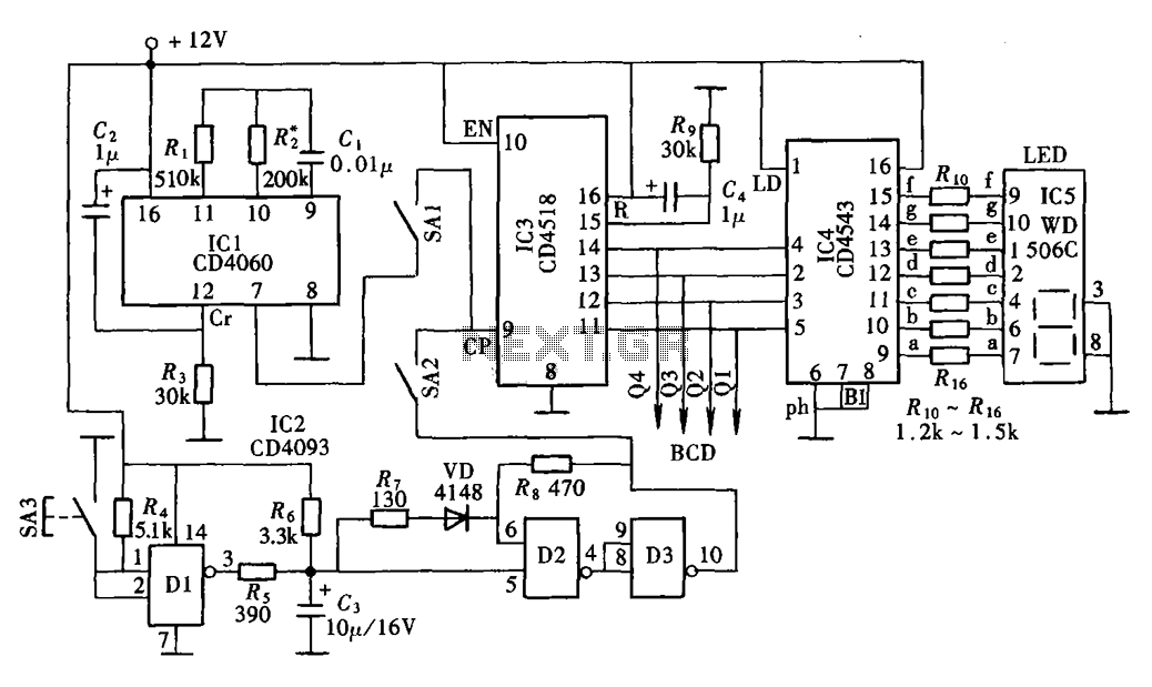
This is a digital clock schematic diagram. The circuit is relatively complex and may pose challenges for beginners due to the intricate connections involving integrated circuits (ICs). The circuit operates with two voltage supply lines. The voltage +5VA powers...
The digital display clock signal source circuit depicted in the figure is derived from a multi-point detection control box within the actual circuit. It primarily comprises an automatic and manual pulse generator, a clock pulse generator, pulse counting elements,...
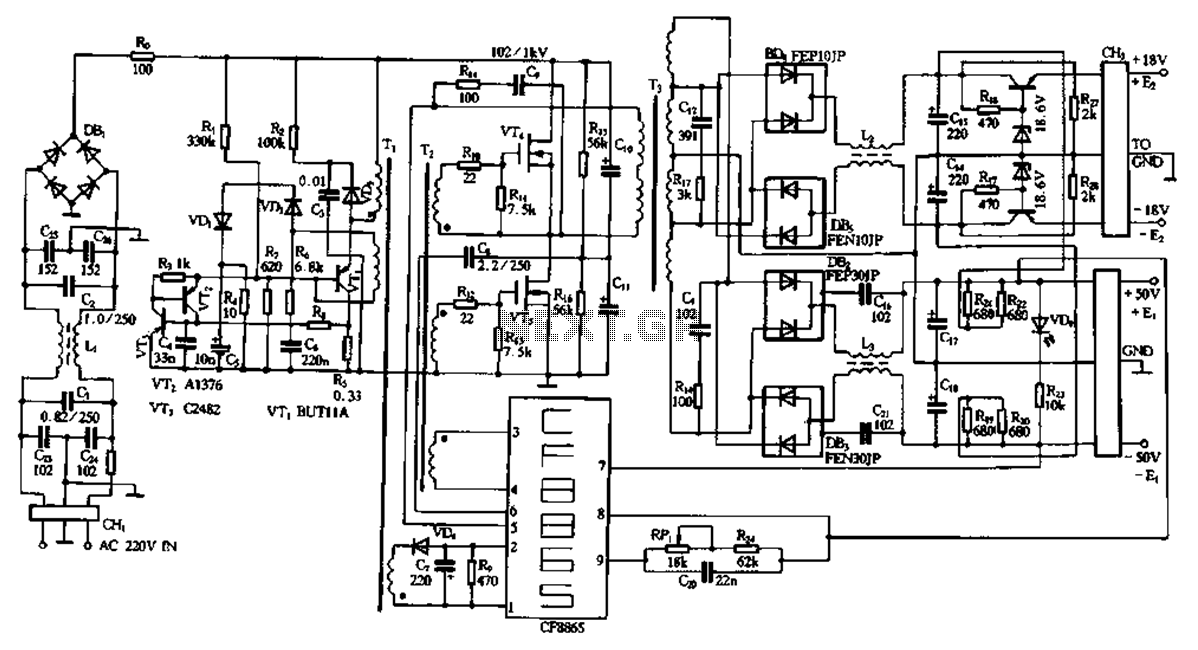
This document describes a specific module utilizing the CF8865 switching power supply circuit, which employs the integrated control module CF8865. In the figure, transistors VT4 and VTs are controlled by the excitation transformer Tz. The output is processed through...
The cost of electricity worldwide has been steadily increasing for over the past 40 years. With the exception of a few periods of stable rates and a handful of minor decreases, electricity prices have risen almost every year since...
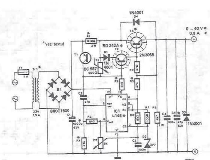
An adjustable laboratory power supply capable of providing an output voltage range from 0 to 60 volts can be constructed using the provided circuit diagram. This power supply can utilize the LM723 chip for lower voltage applications or, for...