
Automatic Electronic Emergency Light Circuit Low Cost

The LED driver section includes a total of twelve 10mm white LEDs, all connected in parallel, with each LED having a 100-ohm resistor in series. The common anode of all twelve LEDs connects to the collector of the PNP transistor T2, while the emitter of T2 is directly linked to the positive terminal of a 6V battery. The unregulated DC voltage generated at the cathode junction of the bridge rectifier is delivered to the base of transistor T2 via a 1kΩ resistor. When mains power is present, the base of T2 remains high, preventing conduction and keeping the LEDs off. Conversely, during a mains failure, the base of T2 goes low, allowing it to conduct and illuminating all twelve LEDs (LED1 through LED12). The mains power supply charges the battery while keeping the LEDs off due to T2 being in a cutoff state. Upon mains failure, the charging section ceases operation, and the battery power causes the LEDs to light up. The circuit should be assembled on a general-purpose PCB and housed in a cabinet with sufficient space for the battery and switches. The LEDs should be mounted in such a way that they illuminate the room. A hole must be drilled in the cabinet to allow for the connection of the 230V AC input to the primary of the transformer. This circuit has been tested with twelve 10mm white LEDs, but additional LEDs can be used as long as the total current consumption does not exceed 1.5A. The driver transistor T2 is capable of delivering up to 1.5A with an appropriate heat sink.
The charger power supply section operates by converting AC voltage to a regulated DC voltage suitable for charging a battery. The LM317 regulator is adjustable, providing flexibility in the charging voltage to accommodate different battery types. The bridge rectifier ensures that the output is a unidirectional current, while the filter capacitor smooths the voltage to minimize fluctuations that could affect charging performance.
The LED driver section is designed to operate under two conditions: when mains power is available and when it is not. The use of a PNP transistor allows for easy switching based on the presence of mains voltage. The inclusion of a resistor at the base of the transistor ensures that it operates within safe limits, preventing damage from excessive current. This design also incorporates safety features, such as the zener diode, which protects the battery from overcharging by diverting current when the battery reaches its maximum voltage.
Overall, this circuit provides a reliable solution for battery charging and LED illumination, suitable for various applications where backup lighting is necessary during power outages. Proper thermal management for the transistor and careful assembly will ensure optimal performance and longevity of the circuit.The circuit comprises two sections: charger power supply and LED driver. The charger power supply section is built around 3-terminal adjustable regulator (IC1) LM317, while the LED driver section is built around transistor BD140(T2). In the charger power supply section, input AC mains is stepped down by transformer to deliver 9V, 500mA to the bridg
e rectifier, which comprises diodes (IN4007x4). Filter capacitor (25v/1000uf)eliminates ripples. Unregulated DC voltage is fed to input pin 3 of IC1 and provides charging current through diode IN4007(D5) and limiting resistor (16ohm)R16. By adjusting preset 2. 2K(VR1), the output voltage can be adjusted to deliver the required charging current. When the battery gets charged to 6. 8V, zener diode conducts and charging current from regulator (IC1) finds a path through transistor BC547(T1) to ground and it stops charging of the battery.
The LED driver section uses a total of twelve 10mm white LEDs. All the LEDs are connected in parallel with a 100-ohm resistor in series with each. The common-anode junction of all the twelve LEDs is connected to the collector of pnp transistor T2 and the emitter of transistor T2 is directly connected to the positive terminal of 6V battery. The unregulated DC voltage, produced at the cathode junction of Bridge(Diodes), is fed to the base of transistor T2 through a 1k resistor.
When mains power is available, the base of transistor T2 remains high and T2 does not conduct. Thus LEDs are off. On the other hand, when mains fails, the base of transistor T2 becomes low and it conducts. This makes all the LEDs (LED1 through LED12) glow. The mains power supply, when available, charges the battery and keeps the LEDs off as transistor T2 remains cut-off. During mains failure, the charging section stops working and the battery supply makes the LEDs glow. Assemble the circuit on a general-purpose PCB and enclose in a cabinet with enough space for battery and switches.
Mount the LEDs on the cabinet such that they light up the room. A hole in the cabinet should be drilled to connect 230V AC input for the primary of the transformer. I have tested the circuit with twelve 10mm white LEDs. You can use more LEDs provided the total current consumption does not exceed 1. 5A. Driver transistor T2 can deliver up to 1. 5A with proper heat-sink arrangement. 🔗 External reference
Related Circuits
This circuit gives a low-level output when sufficient lighting is present, functioning as a light detector. It can issue a command to turn on lights when darkness falls. Its output is compatible with TTL levels, providing a low logic...
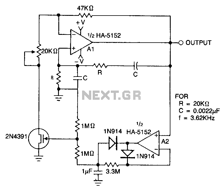
This circuit employs an HA-5152 dual operational amplifier and a field-effect transistor (FET) to create a low-voltage, low-power Wien bridge sine-wave oscillator. The frequency of oscillation is controlled by resistors and capacitors, while the FET functions as a voltage-controlled...
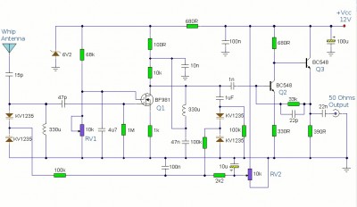
This is a booster antenna circuit designed for frequencies ranging from 550 kHz to 1650 kHz, aimed at amplifying signals received from a telescopic antenna. It covers the medium waveband within this frequency range. To drive low impedance (50...
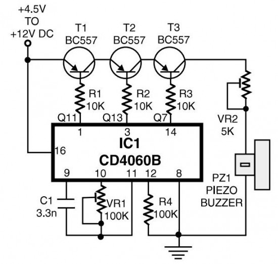
The circuit generates pulses of 1.25 Hz from pin 1 and 20 Hz from pin 14. The three output pins of IC1 are connected to the base terminals of transistors T1, T2, and T3 through resistors R1, R2, and...
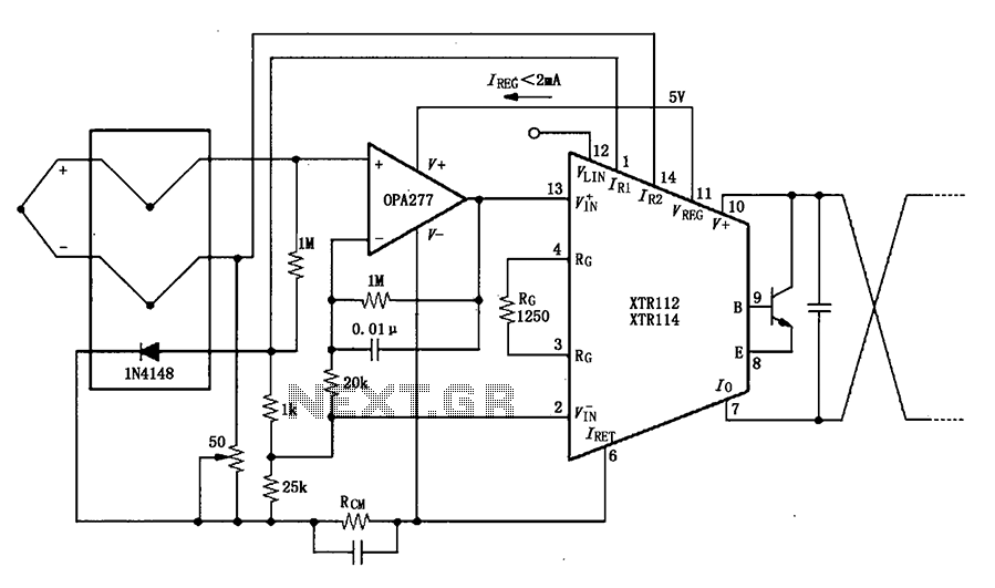
The OPA277 is configured as an inverting amplifier. This inverting amplifier utilizes high input impedance characteristics to minimize loop thermocouple offset drift. A 50-ohm potentiometer is included for calibration, allowing for the adjustment of the inverting input of the...
A high voltage power supply is a valuable source that can be effectively used in various applications, such as biasing gas-discharge tubes and radiation detectors. This type of power supply can also serve as a protective measure, such as...
Warning: include(partials/cookie-banner.php): Failed to open stream: Permission denied in /var/www/html/nextgr/view-circuit.php on line 713
Warning: include(): Failed opening 'partials/cookie-banner.php' for inclusion (include_path='.:/usr/share/php') in /var/www/html/nextgr/view-circuit.php on line 713