
Booster Antenna Circuit 550Khz to 1650Khz
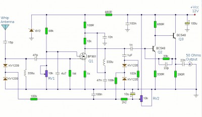
The booster antenna circuit operates effectively within the specified frequency range, utilizing a telescopic antenna as its input source. The BF981 MOSFET serves as the initial amplification stage, where its output impedance is increased through the composite configuration of Q2 and Q3. The common emitter arrangement of Q2 facilitates significant voltage amplification, while Q3's emitter follower configuration ensures that the output remains low impedance, making it suitable for connection to 50-ohm receivers.
The gain control component, RV1, allows users to fine-tune the circuit's response to varying signal strengths. This feature is particularly beneficial in scenarios where signal conditions fluctuate, enabling the circuit to adapt dynamically to weak or strong signals. The dual-gate MOSFET TR1 introduces additional versatility, as it allows for independent control of the input signal and the gain control voltage. The double-tuning mechanism, utilizing the 330 µH coil and KV1235 varicap diodes, enhances the circuit's selectivity, ensuring that it can effectively discriminate between signals within the medium waveband.
Stability is a critical aspect of the design, achieved through the inclusion of a 6.2V zener diode, which provides a regulated power supply to the MOSFET stage. This regulation helps to maintain consistent performance across varying environmental conditions. Furthermore, the design's adaptability to different frequency bands, by altering the coil values, adds to its utility, making it a versatile solution for various radio applications. Overall, this booster antenna circuit represents a well-engineered approach to signal amplification in the medium wave frequency range.Here is abooster antennacircuit for 550Khz to 1650Khz. to amplify the input from a telescopic antenna. cover the medium waveband from about 550Khz to 1650Khz. To drive low impedance (50 ohm) receivers, the medium output impedance of the BF981 stage is enhanced by the composite amplifier made from Q2 and Q3. Q2 is operating in common emitter boosti ng voltage levels by just over 2, Q3 is operating in emitter follower providing thebooster antennacircuit with low output impedance. RV1 is the gain control allowing weak signals to be amplified or strong signals to be attenuated. The control voltagebooster antennais applied to gate 2 of TR1, a dual-gate MOSFET, the signal voltage applied via gate 1; the input signal being double tuned via the 330uH coil and the two KV1235 varicap diodes at the MOSFET`s input and by the same components at the BF981 MOSFET`s drain terminal.
Both tuned circuits provide high selectivity across the entire tuning range. To aid stability the MOSFET stage is fed from a 6. 2V zener stabilized supply. Finally this active booster antenna can be used on other bands by changing the values of the 330uH coils. Here is a schematic booster antenna circuit: We aim to transmit more information by carrying articles.
Please send us an E-mail to wanghuali@hqew. net within 15 days if we are involved in the problems of article content, copyright or other problems. We will delete it soon. 🔗 External reference
Related Circuits
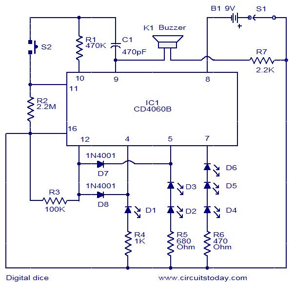
This is a simple and easy-to-construct digital dice circuit. The circuit is based on a single IC, CD4060B. The dice consists of six LEDs marked D1 to D6. The number of LEDs glowing indicates the numeral. The heart of...
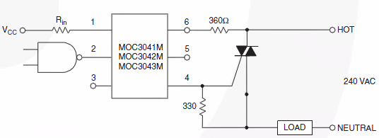
Switch 50V AC voltage. The maximum current drained will be 5A, with a frequency of 50Hz. The switching speed is not critical and can be slow, which is acceptable for the application. Initially, a solid-state relay (SSR) was considered...
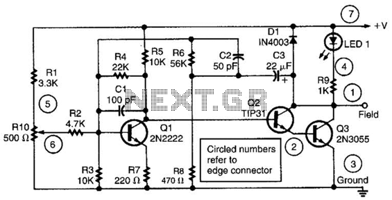
This alternator regulator utilizes a 3-transistor DC amplifier and is designed for a pulled-up field system, where one side of the alternator field returns to the +12V supply, and the other end is pulled toward ground. The circuit monitors...
This circuit is similar to the previous one but employs positive feedback to enhance the amplitude delivered to the speaker. It was adapted from a small five-transistor radio that utilizes a 25-ohm speaker. In the prior circuit, the load...

This design outlines a phone bug circuit. The wireless telephone line spy circuit is capable of transmitting phone conversations to a nearby FM radio. The circuit must be connected to a standard phone line. In the circuit, the first...
This is a component of a 100W RF amplifier. This circuit is constructed using the RF power transistor BLY94. Components include the BLY94 transistor, inductor, and others. The 100W RF amplifier circuit utilizing the BLY94 transistor is designed to amplify...