
XTR112 114 thermocouple measuring circuit diagram of a loop
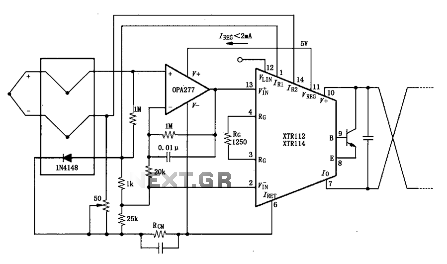
The OPA277 operational amplifier is designed for precision applications, featuring low offset voltage and drift, making it ideal for use in thermocouple signal conditioning. The inverting amplifier configuration allows the circuit to effectively process signals from a J-type thermocouple, which is commonly used in temperature measurement due to its wide operating range and good accuracy.
In this circuit, the high input impedance of the OPA277 minimizes the loading effect on the thermocouple, ensuring that the temperature readings remain accurate. The inclusion of a 50-ohm potentiometer enables fine-tuning of the amplifier's biasing conditions, which is crucial for calibrating the output current to match the specific characteristics of the thermocouple being used. The output current range of 4 to 20 mA is a standard for many industrial applications, facilitating easy integration with control systems and data acquisition devices.
The circuit design should also account for any potential noise and interference, which can affect the accuracy of the temperature readings. Proper layout techniques, such as minimizing loop areas and using twisted pair wiring for the thermocouple connections, can help mitigate these issues. Additionally, the power supply for the OPA277 should be stable and free from fluctuations to maintain the precision of the output signal.
Overall, this inverting amplifier configuration with the OPA277 provides a reliable solution for converting thermocouple signals into a standardized current output, suitable for various monitoring and control applications in industrial environments. As shown, the OPA277 constitute inverting amplifier, inverting amplifier use high input impedance characteristics can be reduced and the loop thermocouple offset drift. 50 pote ntiometer for calibration, adjustable-inverting input of the amplifier bias so that J-type thermocouple in the operating temperature range corresponding to the output current 4 ~ 20mA.
Related Circuits
This circuit is very basic to build. To open a the lock which is connected to the K1 Load you must press each momentary switch in the correct sequence. The sequence used in this circuit is S1,S2,S3,S4. If any...
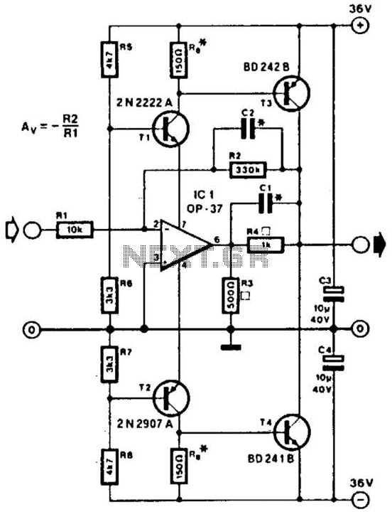
This line driver is capable of driving low-impedance lines with a maximum output of 70 V peak-to-peak. IC1 functions as a low-noise operational amplifier suitable for operation at 15 V. T1 and T2 serve as voltage regulators for the...
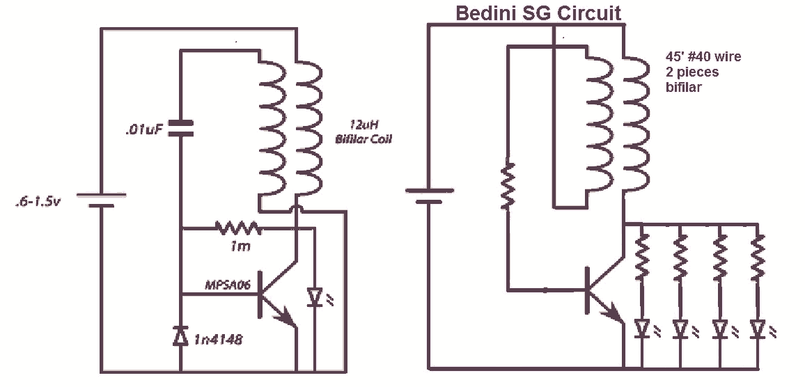
It would be beneficial to obtain schematics of the Joule Thief and Bedini oscillator circuit connections. This is an area that has not been previously explored. The schematic on the left was sourced from the Energetic Forum, while the...
The protection circuit output amplifiers and speakers has some interesting features such as isolating the speaker from the amplifier output when shown a continuous trend in output or when the temperature gets too much cooler while providing a time...
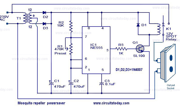
The circuit diagram of a mosquito repellent power saver circuit is provided along with a detailed explanation. The mosquito repellent power saver circuit is designed to efficiently operate a mosquito repellent device while minimizing energy consumption. This circuit typically integrates...
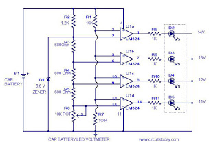
This circuit is a practical device that, when installed in a vehicle, displays the voltage of the car battery using an LED dot display. The meter circuit utilizes four comparators formed from a quad op-amp, specifically the LM324. The...