
Automatic emergency lamp circuit
The automatic emergency lamp circuit is a practical application of electronic components to create a reliable lighting solution for low-light environments. The circuit is designed to operate autonomously, ensuring that emergency lighting is available when needed without manual intervention.
The power supply circuit is essential for providing the necessary voltage and current to the entire system. It typically consists of a transformer, rectifier, and filter capacitor, which convert the AC mains voltage to a stable DC voltage suitable for the operation of the electronic components.
The light control circuit employs a phototransistor (VSL) that acts as a light sensor. When ambient light levels are high, the VSL's low resistance prevents current from flowing through the base of the transistor VT1, keeping it in the off state. This effectively disables the emergency lamp during the day or in well-lit conditions, conserving energy and extending the life of the lamp.
As night falls or when light levels drop, the resistance of the phototransistor VSL increases, allowing more current to flow to the base of VT1. This change in state triggers the transistor to turn on, activating the electronic switching circuit. The electronic switch integrated circuit is responsible for controlling the power delivered to the EL lamp, ensuring it lights up when required.
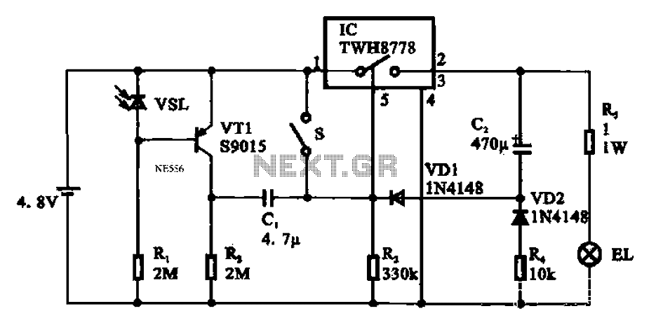
The design of this circuit emphasizes efficiency and reliability, making it suitable for various applications, including home emergency lighting, outdoor lighting, and safety lighting in public areas. The use of an integrated circuit simplifies the design and reduces the number of discrete components, which can enhance reliability and reduce overall size. This automatic emergency lamp circuit exemplifies the integration of sensors and control systems in modern electronic design, providing an essential service in emergency situations. Automatic emergency lamp circuit It shows the electronic switch integrated circuit of automatic emergency lamp circuit. Made into the circuit with automatic emergency lights in Bai Tianguang line it does not work enough, when the light is low light automatically at night. The circuit shown in Figure 1148, primarily by the power supply circuit, light control circuit, and the like of the electronic switching circuit. During the day or light intensity is high, phototransistor VSL resistance value is small, the transistor VT1 is off, the subsequent circuit does not operate, licensing EL lamp is not lit; when the light dimmed to night.
VSL resistance value is increased, the transistor VTI base sufficient to promote its conduction voltage value, after the opening stage circuit starts to enter the work state, the electronic switch integrated circuit inside the electronic switch is turned on, the lamp EL light.
Related Circuits
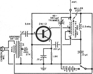
It had been a little over a decade since the invention of the transistor when this article appeared in the August 1959 edition of Popular Electronics. Transistors were still a mystery to many, including engineers, technicians, and hobbyists. Author...
This schematic represents an FM transmitter capable of delivering an output power between 3 to 3.5 W, operating within the frequency range of 90 to 110 MHz. While the stability of the circuit is acceptable, the integration of a...
This circuit is used to power an LED with a voltage of 230V. The 230V must be reduced to meet the LED's voltage requirements. To achieve this, a circuit is necessary as described below. The circuit designed to power an...
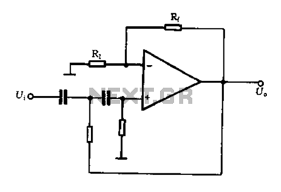
A typical two high-pass filter circuit. A high-pass filter (HPF) is an electronic circuit that allows signals with a frequency higher than a certain cutoff frequency to pass through while attenuating signals with frequencies lower than the cutoff frequency. A...
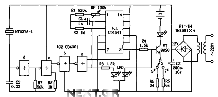
The CD4001/CD4541 nickel-cadmium battery automatic charger circuit is illustrated in the figure. This circuit is designed for charging up to seven rechargeable nickel-cadmium batteries. It features automatic charging with constant current characteristics. Once powered, the circuit activates an internal...
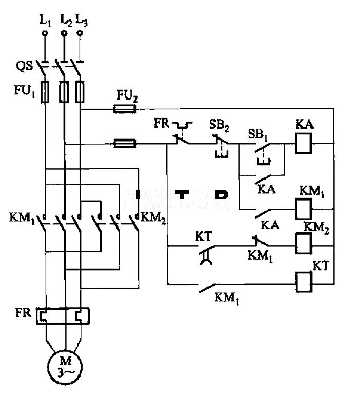
The circuit illustrated in Figure 3-127 utilizes a time relay (KT) in place of a speed relay. The timing duration is adjustable and typically set between 1 to 2 seconds. This circuit is designed to operate effectively in dusty...