
Transistor Circuits

Transistor circuits form the foundation of modern electronics, and understanding their operation is crucial for effective design and implementation. The grounded emitter configuration discussed in the article is one of the most widely used transistor amplifier designs, characterized by its ability to provide voltage gain and moderate input impedance while maintaining a low output impedance. In this configuration, the emitter terminal is connected to ground, allowing the input signal to be applied between the base and emitter, while the output is taken from the collector.
In this setup, biasing is critical for ensuring the transistor operates in the active region, where it can amplify signals. The base-emitter junction is typically forward-biased, allowing current to flow from the base to the emitter, while the collector-emitter junction is reverse-biased, enabling control of the collector current through the base current. The relationship between these currents is governed by the transistor's current gain, denoted as β (beta), which defines how much the base current is amplified in the collector.
When designing a one-transistor amplifier, attention must be paid to the selection of resistors for biasing and load purposes. The collector resistor plays a vital role in determining the output voltage swing, while the emitter resistor can stabilize the bias point against variations in transistor parameters or temperature. Coupling capacitors are also essential, as they block DC while allowing AC signals to pass, ensuring that the amplifier only amplifies the desired signal without affecting the biasing conditions.
Testing transistor characteristics typically involves measuring parameters such as hFE (forward current gain), input and output impedances, and frequency response. Understanding these characteristics allows for the optimization of circuit designs to meet specific application requirements, whether for audio amplification, signal processing, or switching applications.
The dialogue format employed in the article effectively illustrates the learning process, emphasizing the importance of practical knowledge and hands-on experience in mastering transistor technology. This approach encourages readers to engage with the material actively, fostering a deeper understanding of the principles that govern transistor operation and circuit design.It had been only a little over a decade since the transistor was invented when this article appeared in the August 1959 edition of Popular Electronics. Transistors were still a mystery to most people, including engineers, technicians, and hobbyists. Author James Butterfield takes a unique approach in presenting the material by writing it as a dialog between an instructor and a student.
If you are also new to transistors, this will be worth your while to read. Pete introduces Johnny to the grounded emitter circuit. Its "why`s" and "how`s" are investigated and the not-too-mysterious matters of base and collector bias are discussed. The rule is, as Pete explains it, "Let Ohm`s Law be your guide. " Trying to design a one-transistor amplifier, Johnny gets tangled up with input and output impedance problems.
Pete straightens him out with some important "do`s" and "don`ts" in getting a signal in and out of a transistor. The transistorized approach to filters and tone and volume controls is detailed by Pete with some practical suggestions on the testing of transistor characteristics.
Coupling problems are discussed, and Pete draws up a chart that matches the coupling capacitor to the collector resistor "That`s an amplifier " snorted Johnny. "You must have dreamed up that circuit during a fit of indigestion! Anybody knows even the simplest transistor amplifiers are bristling with resistors and oversize coupling capacitors.
And where`s the output transformer for the speaker " "Don`t need any. " Pete clipped on the ground lead from the audio generator and inserted a. 1- µf. capacitor in series with the other lead. "Trouble with most of you experimenters is that you just copy diagrams - maybe change `em a little here and there to see what happens - but you never bother to find out what really makes things tick. " He touched the other end of the capacitor to his input lead, and the speaker sang with a clear tone.
"Pete, I`ve got six books on transistors, and I still don`t know what I`m doing, " complained Johnny. "They are either so simplified that they don`t say anything - or they`re crammed with equations from stem to stern, " "Nothing wrong with equations.
" Pete was busy tidying up his workbench. "But you don`t always need `em. I threw this amplifier together without fancy calculations - just horse sense. Let`s go into the kitchen for coffee, and I`ll try to fill you in on the practical side of transistors. " "First off, " said Pete settling in a chair, "You know that a transistor is sort of like a pair of diodes, back to back, like this.
" He sketched rapidly on a napkin. "The way I`ve shown it here, the transistor is a p-n-p unit. To get an n-p-n job, you flip both diodes end-for-end. We`ll dig deeper into this later-but for now, just remember when positive voltage is on the p section and negative voltage on the n section, the transistor conducts. " "I suppose the lead in the middle is the base, " said Johnny. "But which is the collector and which is the emitter Your diagram doesn`t show any difference. " "Here`s something that will probably surprise you, Johnny. The collector and the emitter could be changed around and the transistor would still work! But since the manufacturer normally builds the collector bigger and stronger than the emitter - take his advice and use the collector lead as the collector.
"The real difference between the collector and emitter is in the way we treat them. The emitter is biased to allow maximum current flow (forward bias) and the collector, on the other hand, is back-biased for minimum current. " "Hey, " Johnny cut in. "Wouldn`t a heavy cu 🔗 External reference
Related Circuits
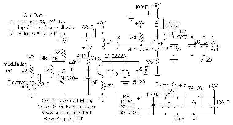
Here are some utility circuits for use with the Ramsey FM10a, and other small FM stereo transmitter kits. This information may be helpful for setting up a micro powered FM radio station. The FM10a and similar kits tend to...
At the beginning of the design process, the designer must determine which circuit structure is appropriate for a specific purpose. During this phase, numerical and symbolic analysis are of limited utility. There are no numerical values available for conventional...
AN79 Linear Technology AN79 modifies methods presented in AN74, allowing for the verification of 30 nanosecond amplifier settling times with 0.1% resolution. The sampling-based technique used is detailed, and results are presented. Appendices cover oscilloscope overdrive issues, the construction...
The following circuit presents a Mini Audio Amplifier Circuit Schematic Diagram. Features include a power consumption of less than 3mA, a small output, and the use of a push-pull configuration. The Mini Audio Amplifier Circuit is designed to amplify low-level...
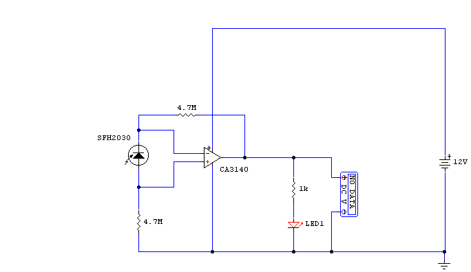
While developing an infrared (IR) extender circuit, a method was needed to measure the relative intensities of different infrared light sources. This circuit utilizes an SFH2030 photodiode as the infrared sensor. A CA3140 MOSFET operational amplifier is employed in...
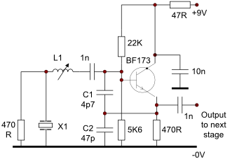
This circuit operates effectively from low frequencies up to at least 120 MHz using series resonant crystals in their fundamental or overtone mode. The output can be obtained from the feedback tap, a low impedance winding on L2, or...