
3W FM Transmitter circuit
The FM transmitter circuit typically consists of several key components, including an oscillator, modulator, and power amplifier. The oscillator generates a carrier frequency within the specified range, while the modulator encodes the audio signal onto the carrier wave. The power amplifier then boosts the modulated signal to the desired output power level.
In this design, the oscillator may employ a Colpitts or Hartley configuration, which is known for its stability and ease of tuning. The frequency can be adjusted using variable capacitors or inductors, allowing for fine-tuning within the 90 to 110 MHz range.
The modulator section can utilize a transistor or an integrated circuit that modulates the amplitude or frequency of the carrier signal based on the input audio signal. This modulation is crucial for transmitting audio over the FM band effectively.
The power amplifier is responsible for increasing the output signal to the specified power level. It may utilize a push-pull configuration to improve efficiency and linearity, ensuring minimal distortion of the audio signal during transmission.
Incorporating a PLL into this circuit can significantly improve frequency stability and drift compensation. The PLL can lock onto the desired frequency and maintain it against variations in temperature or component aging. This addition would enhance the overall performance of the FM transmitter, making it more reliable for consistent broadcasting.
Additional components such as filters may be included to suppress unwanted harmonics and ensure compliance with regulatory standards for FM transmission. Proper grounding and layout considerations are essential to minimize interference and maintain signal integrity throughout the circuit.This is the schematic for an FM transmitter with 3 to 3.5 W output power that can be used between 90 and 110 MHz. Although the stability isn`t so bad, a PLL can be used on this circuit.. 🔗 External reference
Related Circuits

A Siemens SLB0586A IC enables the creation of a straightforward touch-controlled dimmer circuit. This circuit regulates a triac AC switch, allowing control of loads ranging from 10 to 400 W. The Siemens SLB0586A integrated circuit is designed to facilitate the...
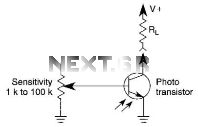
A variable resistor is utilized to adjust the light-level response of a phototransistor. Phototransistors exhibit higher light sensitivity compared to photodiodes; however, they typically demonstrate a lower frequency response. A variable resistor, often referred to as a potentiometer or rheostat,...
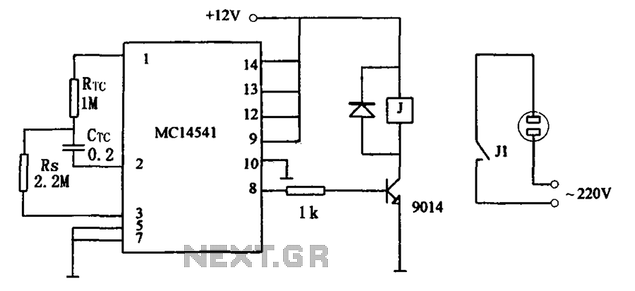
The circuit illustrated in FIG MC14541 is a straightforward timing circuit utilizing the MC14541 integrated circuit (IC). By adjusting the parameter map, the timing can be set for a duration of 3 hours, with options to select various RTC,...
This circuit utilizes a ceramic tuning resonator with a frequency of 3.587 MHz, alongside resonator filters available at frequencies of 5.5 MHz, 7.7 MHz, and 10.7 MHz. The transmission range of the device is approximately 2-4 km. The circuit...

Many enthusiasts utilize their PCs as data loggers, controllers, or web servers. In such instances, it is crucial to ensure that the machine remains powered for as much time as possible, even during a power outage or if the...
The circuit is a bistable circuit where each bistable unit is controlled by high and low output levels. When power is supplied to the circuit, current flows through components R13, CL, and VD to VD2 for full-wave rectification. The...