
Automatic Fader Circuit
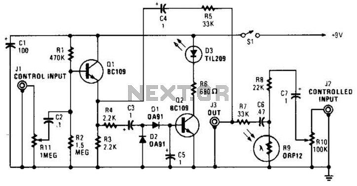
This circuit operates on the principle of audio signal modulation using a combination of amplification, rectification, and light-dependent resistive feedback. The initial audio signal enters the control channel, where it is processed by diodes D1 and D2. These diodes serve to rectify the audio waveform, converting the alternating current (AC) signal into a direct current (DC) level, which is necessary for controlling the subsequent components in the circuit.
Transistor Q2 is employed to switch LED D3 on and off based on the rectified audio level. The brightness of LED D3 directly influences the resistance of the light-dependent resistor R9. As the audio signal increases, the LED brightness increases, leading to a further decrease in resistance of R9. This feedback mechanism plays a crucial role in dynamically adjusting the audio gain through R11.
The configuration of R11 allows for fine-tuning of the audio gain, making it possible to control how much audio from the input at J2 is allowed to pass through to J3. When R11 is set to a higher value, the output from Q1 increases, allowing more audio to reach J3. Conversely, as R9 shunts audio to ground, it effectively reduces the audio signal at J3, contributing to the fade effect.
The design of this circuit is particularly useful in applications where audio fading is required, such as in audio mixing consoles or sound effect generators. The interaction between the light-dependent resistor and the LED creates a smooth transition in audio levels, enhancing the overall listening experience. In this circuit, audio fed to the control channel is amplified and rectified by Dl and D2. This dc level activates LED D3 via Q2. The light from D3 causes R9, a light-dependent resistor to decrease resistance. As Rll (audio gain) is set higher, more audio is present at the output of Ql. Audio fed into J2 is shunted to ground via R9 and less of this audio appears at J3. Therefore, audio at Jl controls the audio level fed to J3 from J2 andjproduces a fade effect. 🔗 External reference
Related Circuits
In addition to its primary function as a headphone amplifier, the circuit is suitable for various applications requiring a wide bandwidth low power amplifier. It is constructed using an operational amplifier (op-amp), with its output current enhanced by a...
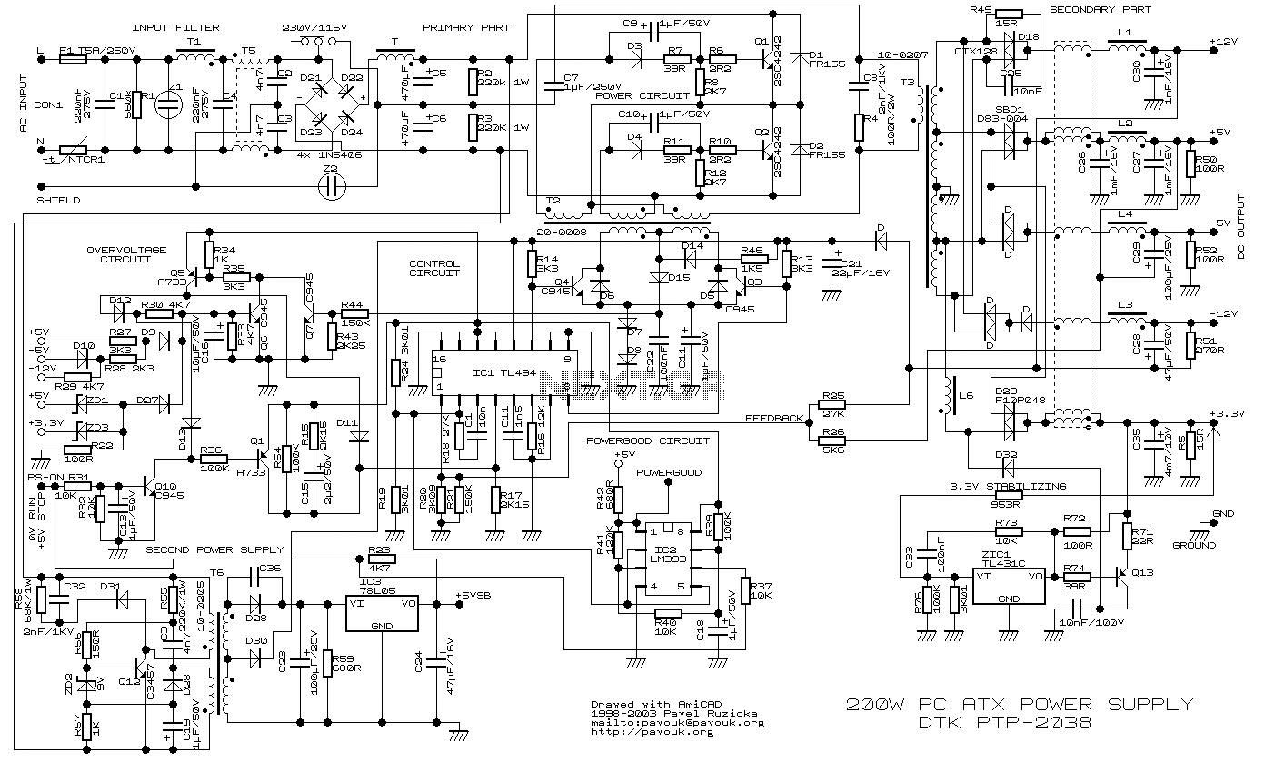
200W ATX Power Supply Circuit power supply. Visit the page for an explanation of the power supply circuit diagram. Here is a simple battery monitor circuit in which the LED continues flashing until the battery voltage is above a...
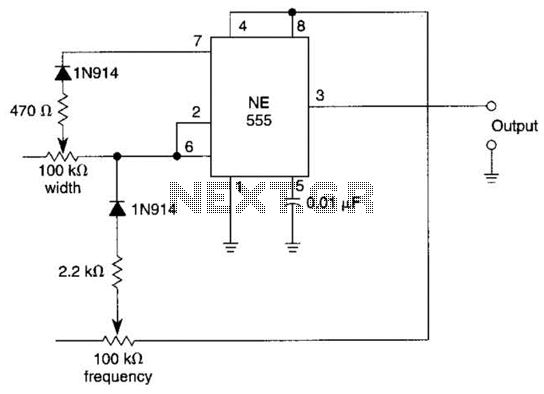
In this multivibrator circuit, frequency and pulse width can be separately controlled by using steering diodes (1N914) and two potentiometers. This multivibrator circuit utilizes steering diodes, specifically the 1N914 type, to enable independent control over both the frequency and pulse...
It is a wireless doorbell with a cost of about $10.00. This product encourages a shift in approach to building projects, utilizing such items to learn about their functions and modify them to meet specific needs. The doorbell incorporates...
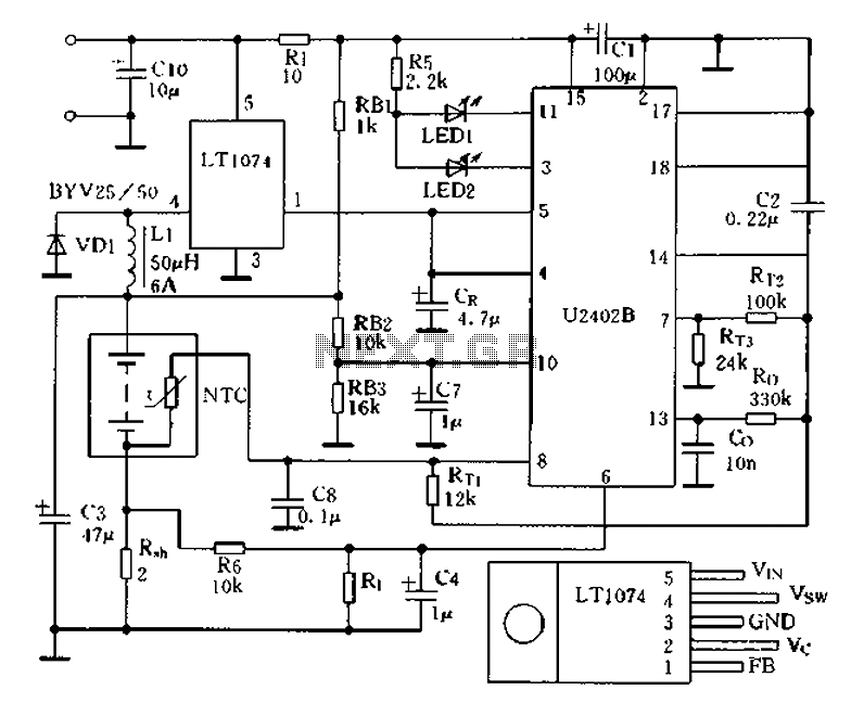
Charging circuit from the DC power supply switching power supply control The charging circuit described is designed to operate with a DC power supply, utilizing a switching power supply control mechanism. This type of circuit is commonly employed in applications...
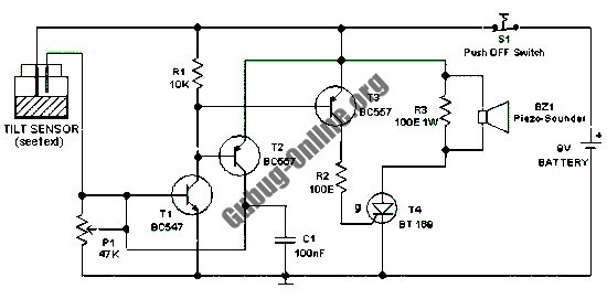
This design features a simple circuit for a tilt sensor alarm that can be constructed using readily available and inexpensive components. The circuit is based entirely on transistor technology. The homemade tilt sensor for this circuit utilizes a standard...