
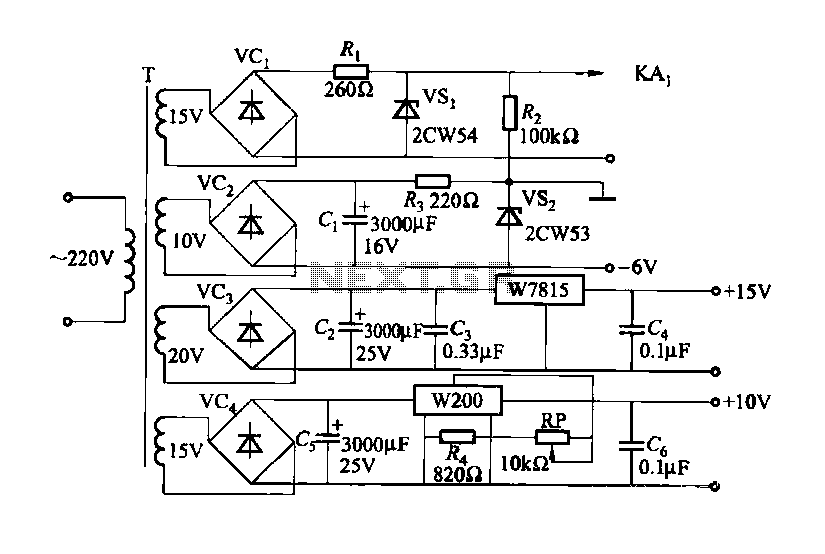
Charging circuit from the DC power supply switching power supply control
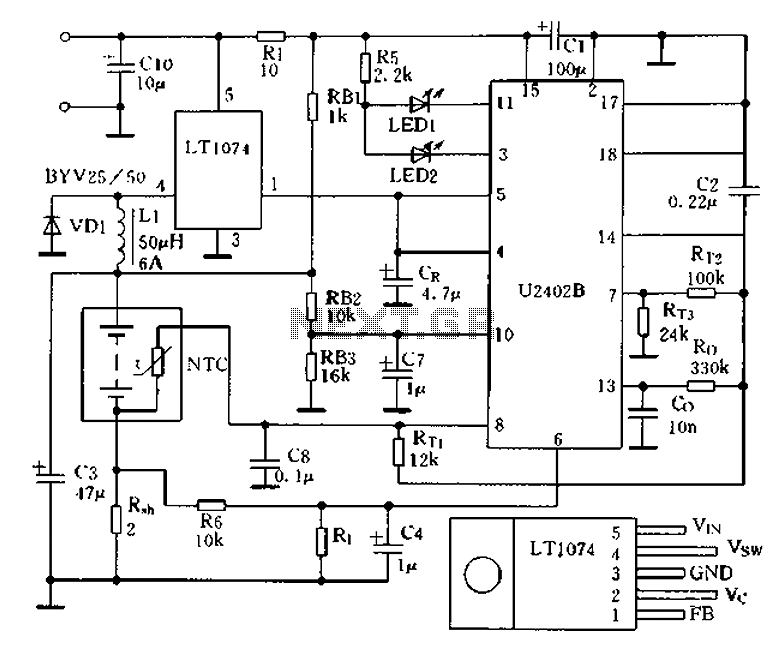
The charging circuit described is designed to operate with a DC power supply, utilizing a switching power supply control mechanism. This type of circuit is commonly employed in applications where efficient energy transfer and regulation are critical, such as in battery charging systems.
The circuit typically consists of several key components, including a switching regulator, input and output capacitors, diodes, and control logic. The switching regulator is responsible for converting the input DC voltage to a regulated output voltage suitable for charging a battery or powering a load. It operates by rapidly switching the input voltage on and off, which allows for efficient energy conversion and minimal heat generation.
Input capacitors are used to filter the incoming voltage, ensuring a stable supply to the switching regulator. Output capacitors are crucial for smoothing the output voltage and minimizing voltage ripple, which is essential for sensitive electronic components and batteries.
Diodes may be included in the circuit to prevent reverse current flow, protecting the power supply and connected devices from potential damage. The control logic, which may consist of operational amplifiers or microcontrollers, regulates the switching frequency and duty cycle of the regulator, adjusting the output based on the load requirements and battery state.
Overall, this charging circuit is characterized by its ability to efficiently manage power delivery from a DC source, making it suitable for a wide range of applications, including consumer electronics, electric vehicles, and renewable energy systems. Proper design and implementation of the circuit components are essential for achieving optimal performance and reliability. Charging circuit from the DC power supply switching power supply control
Related Circuits
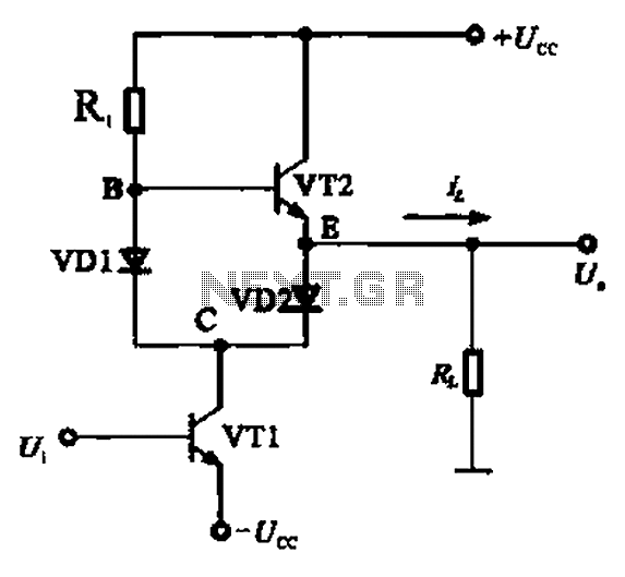
A Class AB output stage circuit is coupled with diodes, as illustrated in Figure 10-8. The static bias circuit for transistor VT1 (not shown) is adjusted so that the output at point E is at ground DC voltage UE....
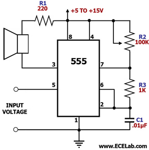
This circuit is designed to power a lamp or other appliance for a specified duration of 30 minutes, after which it automatically turns off. It is particularly useful for nighttime reading, as it can turn off a bedside lamp...
The circuit is designed for a broadband linear detection application with a bandwidth of 10 MHz. It serves as a millivoltmeter measuring instrument suitable for frequencies exceeding 10 MHz. The circuit features a linear detector utilizing operational amplifiers, specifically...
This document outlines a CMOS circuit designed for time adjustment in a spot welder. The circuit allows for the selection of a number of cycles, ranging from 1 to 99, with practical applications typically using around 10 cycles. The...
The objective is to identify a function generator or a voltage-controlled oscillator (VCO) suitable for generating two sine wave sound signals. One waveform should be fixed at a frequency, such as 440 Hz, while the second waveform must be...
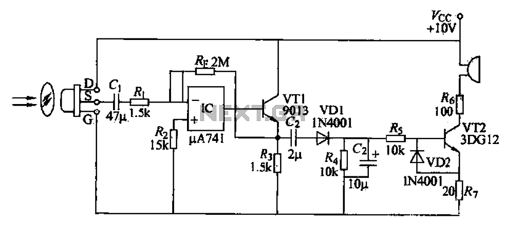
A simple burglar alarm circuit utilizes a pyroelectric sensor (IRA-E100SZI). When human movement is detected, it triggers an electric buzzer alarm. The sensor receives signals through an AC amplifier, which is then converted by a rectifier circuit into a...