
Automatic Fan Control circuit
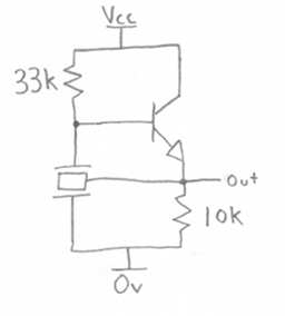
The automatic fan control circuit operates by monitoring the temperature of its environment and activating a 12V DC fan when the temperature exceeds a predetermined threshold. The core component of this circuit is a temperature sensor, which can be a thermistor or an integrated temperature sensor IC, that provides a voltage output proportional to the ambient temperature.
The circuit includes a variable resistor, VR1, which allows the user to set the desired temperature threshold. When the temperature rises above this threshold, the sensor outputs a signal that is processed by a comparator or microcontroller. If the temperature exceeds the setpoint, the output of the comparator or microcontroller will switch on a transistor or a relay, which in turn activates the fan.
The fan continues to operate until the temperature drops below the threshold, at which point the circuit will deactivate the fan to conserve energy and reduce noise. The circuit may also include additional features such as LED indicators to show the operational status of the fan or a hysteresis control to prevent rapid on-off cycling of the fan.
Power supply considerations for this circuit involve ensuring that the fan and control circuitry are adequately powered by a stable 12V DC source. Proper heat dissipation methods should also be implemented to ensure reliable operation of the fan and control components. Overall, this automatic fan control circuit is essential for maintaining optimal temperature conditions in various electronic applications, enhancing performance and longevity of the components being cooled.Automatic Fan Control circuit. This circuit is ON / OFF 12V DC fan or die CPU fan factory IF temperature above normal again temperature.You Can Feed the temperature of VR1. This circuit uses. 🔗 External reference
Related Circuits
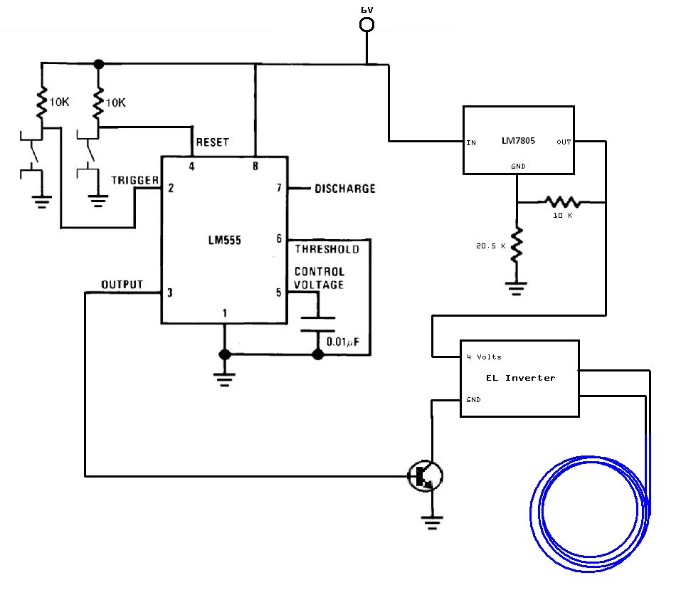
The circuit utilized for this project is quite simple. Some may criticize the omission of decoupling capacitors for the LM7805 voltage regulator. The circuit in question employs the LM7805 voltage regulator, which is designed to provide a stable output voltage...
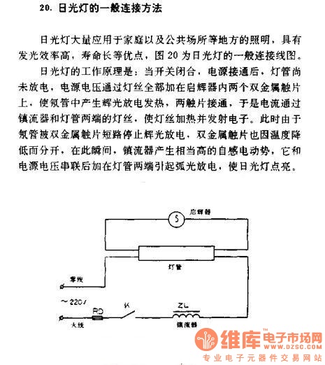
The general connection method for fluorescent lamps is utilized in residential and public lighting applications due to their luminous efficiency and long service life. The general wiring diagram for the lamp is illustrated in Figure 20. The working principle...
A DIY GSM jammer schematic diagram designed specifically for GSM1900 frequencies ranging from 1930 MHz to 1990 MHz. The GSM1900 mobile phone network is utilized in the USA, Canada, and most South American countries. This cell phone jammer is...
A ceramic resonator can be utilized to construct an oscillator. A single digital inverter can be employed to create a Pierce oscillator. To design a Pierce oscillator using a ceramic resonator and a digital inverter, the following components and configurations...
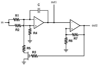
A voltage-controlled oscillator (VCO) is an electronic oscillator designed to control its oscillation frequency through a voltage input. The oscillation frequency is varied by the applied DC voltage, and modulating signals can also be introduced to the VCO for...
This weblog discusses electronic circuit schematics, PCB design, DIY kits, and electronic project diagrams. The circuit diagram presented is for a magnetic proximity switch, which has numerous applications across various fields. The circuit utilizes a magnetic reed switch (S1)...
Warning: include(partials/cookie-banner.php): Failed to open stream: Permission denied in /var/www/html/nextgr/view-circuit.php on line 713
Warning: include(): Failed opening 'partials/cookie-banner.php' for inclusion (include_path='.:/usr/share/php') in /var/www/html/nextgr/view-circuit.php on line 713