
Ceramic Resonator Oscillator Circuit
To design a Pierce oscillator using a ceramic resonator and a digital inverter, the following components and configurations are essential:
1. **Components**:
- **Ceramic Resonator**: This passive component provides the frequency stability and determines the oscillation frequency. The resonator should be selected based on the desired operating frequency.
- **Digital Inverter**: A single CMOS or TTL inverter, such as the 74HC04, will be used to create the oscillator circuit.
- **Capacitors**: Two capacitors (C1 and C2) are required, typically of equal value, to couple the resonator to the inverter and to set the gain and feedback necessary for oscillation.
- **Resistor (R)**: A resistor may be included in parallel with the inverter to help stabilize the oscillation and limit the current.
2. **Circuit Configuration**:
- Connect the output of the inverter to one terminal of the ceramic resonator.
- The other terminal of the resonator should be connected to ground.
- Place the two capacitors (C1 and C2) in series with the resonator, connecting one capacitor to the inverter input and the other to ground.
- Optionally, a resistor can be connected in parallel with the inverter to provide feedback stability.
3. **Operation**:
- When power is applied, the inverter will initially produce a low output, allowing the resonator and capacitors to charge. Once the voltage across the resonator reaches a certain threshold, the inverter output will switch high.
- This feedback mechanism creates a positive feedback loop, causing the inverter to toggle and generate a square wave output at the resonator's fundamental frequency.
- The frequency of oscillation can be adjusted by changing the values of the capacitors or selecting a resonator with a different frequency rating.
4. **Applications**:
- The Pierce oscillator is widely used in clock generation for microcontrollers, frequency synthesis, and other timing applications due to its simplicity and stability.
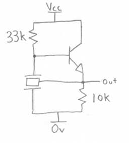
This configuration allows for a compact and efficient oscillator design suitable for various electronic applications. Proper attention to component selection and circuit layout will ensure optimal performance of the oscillator.I am looking to build a oscillator from a ceramic resonator. I know that a single digital inverter can be used to form a Pierce oscillator (hundreds.. 🔗 External reference
Related Circuits
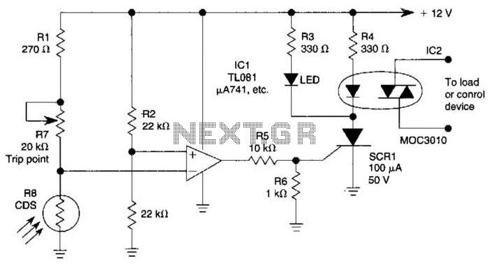
The light-sensitive CDS cell R8 is configured in a bridge circuit with IC1 functioning as a comparator. When light strikes the CDS cell R8, the output of IC1 goes high, triggering SCR1. This action illuminates LED1 and activates opto...
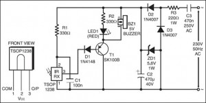
The following circuit illustrates an IR Remote Control Tester Circuit. Features include that transistor T1 conducts during the negative pulse period, and there is a data output pin. The IR Remote Control Tester Circuit is designed to verify the functionality...
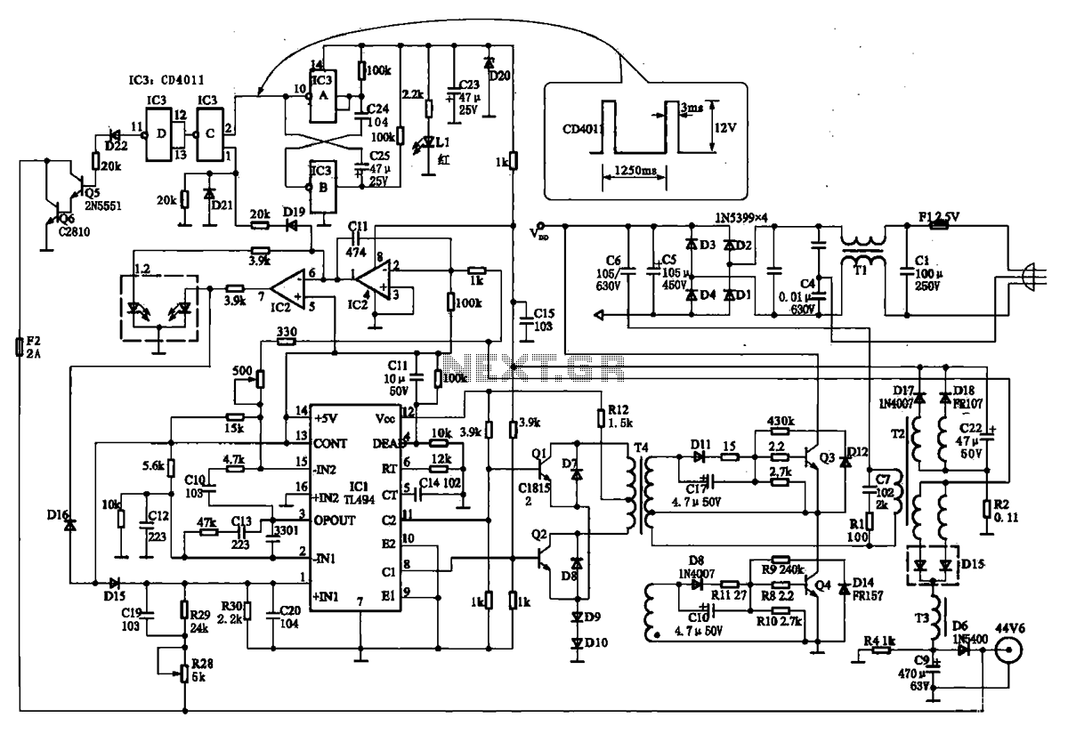
The TN-1 Intelligent Negative Pulse Charging Circuit is a sophisticated device designed for efficient battery charging. It operates as a half-bridge charger, which is a common configuration in such circuits. The negative pulse charging mechanism is facilitated by a...
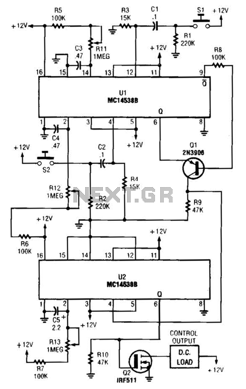
When switch SI is closed, pin 9 of operational amplifier U1 goes low, activating transistor Q1 for a predetermined duration. If switch S2 is closed during this time, transistor Q2 is activated for another predetermined duration. Resistors R1 and...
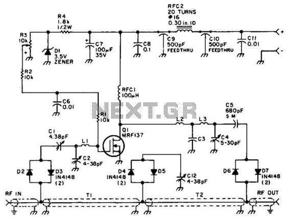
Using a power MOSFET, this amplifier can achieve a 2-W handheld radio power level, increasing it to approximately 10 W on the 2-meter band. A transmission-line RF switch is employed for transmit/receive (T/R) switching. The described amplifier utilizes a power...
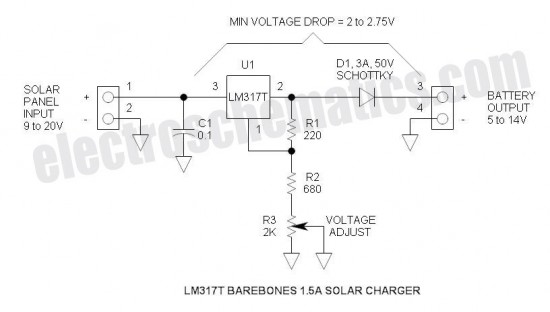
This is the simplest and most affordable solar battery charger that a hobbyist can create. It has some drawbacks compared to other similar controls, but offers unique advantages. The solar battery charger circuit is designed to harness solar energy to...