
Magnetic Proximity Switch Circuit

The magnetic proximity switch circuit is designed for applications where non-contact detection of objects is required. The reed switch (S1) operates by closing its contacts in the presence of a magnetic field, thus providing a reliable method for detecting proximity. The NE555 timer (IC1) is configured in a monostable mode, meaning it generates a single output pulse when triggered. The duration of this pulse is determined by the values of R2 and C2, which can be adjusted to suit the specific timing requirements of the application.
The output pulse from IC1 serves as a trigger for the CD4013 flip-flop (IC2), which operates in toggle mode. This flip-flop allows for the output state to change each time it receives a trigger pulse, making it ideal for applications where a change in state is required with each detection event. The output at pin 1 of IC2 drives the base of transistor Q1, which acts as a switch to control the relay. When Q1 is turned ON, the relay contacts close, allowing current to flow to any connected load, thereby activating it.
The inclusion of LED D1 provides a visual indication of the system's operation. When the proximity sensor is triggered, IC1 outputs a high signal, causing D1 to illuminate, which serves as an immediate feedback mechanism for users to confirm that the switch has been activated.
Overall, this circuit is versatile and can be employed in various applications, such as security systems, automation controls, and industrial sensing devices, where magnetic proximity detection is advantageous. Proper selection of components, including the values of R2 and C2, is crucial to ensure the circuit operates within desired parameters for specific applications.Welcome to the weblog where we discuss about electronic circuits schematics, PCB design, diy kits and electronic projects diagrams. Here is the circuit diagram of a magnetic proximity switch that finds a lot of applications in abounding fields.
The ambit is based on a alluring reed switch(S1) as the adjacency sensor. A monostable multivibrator bas ed on NE555 (IC1) and a toggle cast bomb based on CD4013 (IC2) does the blow of the circuit. When a allurement is accomplished in adjacency of S1 it closes to accord a abrogating activate at pin 2 of IC1. The achievement of IC1 goes top for a time determines by R2 and C2. This clocks the IC2 active as a toggle cast flop. The achievement (pin 1 ) of IC2 goes top and the transistor Q1 is biased to ON. The broadcast is activated and so do the accessories affiliated to the relay. The LED D1 glows if IC1 is triggered. When a allurement is accomplished in adjacency of S1 it closes to accord a abrogating activate at pin 2 of IC1.
The achievement of IC1 goes top for a time determines by R2 and C2. This clocks the IC2 active as a toggle cast flop. The achievement (pin 1 ) of IC2 goes top and the transistor Q1 is biased to ON. The broadcast is activated and so do the accessories affiliated to the relay. The LED D1 glows if IC1 is triggered. 🔗 External reference
Related Circuits
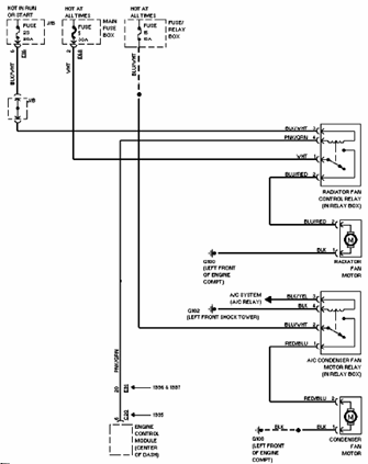
The 1996 Suzuki Esteem Cooling Fan system includes a control relay for the radiator fan (located in the relay box), air conditioning fan motor, radiator fan motor, condenser fan motor, junction box, fuse and relay box, and engine control...

The circuit consists of a DC voltage regulator, a delay circuit, and protection mechanisms for overvoltage and undervoltage. It utilizes the LM7812 integrated voltage regulator to provide a stable 12V output. The protection circuit samples voltage using R2 and...

The circuit operates by detecting a clapping sound through a piezoelectric ceramic sensor, which converts the sound into an electrical signal. This signal is then amplified by the transistor VT1 and fed through a coupling capacitor C1 to the...
Firecrackers are typically ignited using a matchstick or candle. After igniting the fuse, it is necessary to retreat quickly to a safe distance. This method poses safety risks due to the possibility of the firecracker detonating before reaching a...
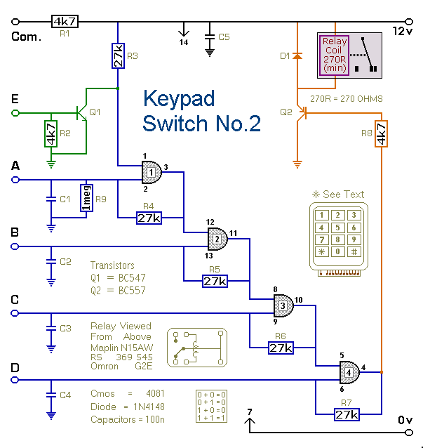
This is a simplified version of the 4-Digit Keypad Controlled Switch. The design has been modified to reduce circuit complexity and the number of components required. Consequently, the code is somewhat less secure, but it should be sufficient for...

Comprehensive information about RF Probe Circuits is available. Users can learn about and download RF Probe Circuit designs online. RF Probe Circuits are essential tools for testing and analyzing radio frequency signals in various applications, including telecommunications, broadcasting, and electronic...