
Automatic Light Controller Using 7806
The circuit utilizes a 78xx series voltage regulator, which is designed to maintain a constant output voltage. The input voltage is processed by a transformer that steps down the AC mains voltage to a manageable level before being rectified into DC. The bridge rectifier configuration ensures that the output voltage is properly filtered and smoothed, providing a stable input for the voltage regulator.
The control mechanism is based on ambient light conditions detected by the LDR1, which serves as a variable resistor. Its resistance changes with light intensity, allowing for automatic control of the circuit. The transistor T1 acts as a switch, effectively grounding the common terminal of the voltage regulator when ambient light is sufficient, thus allowing the circuit to remain off during the day. Conversely, at night, when the light intensity drops, T1 turns off, removing the ground connection from IC1, allowing the full input voltage to reach the output.
The output of the voltage regulator is then used to drive transistor T2, which controls the relay RL1. The relay serves as a switch to connect the light bulb to the mains supply, completing the circuit. The inclusion of a zener diode (ZD1) in the base circuit of T2 ensures that the transistor operates within safe limits, preventing damage from voltage spikes.
The design also incorporates an LED indicator (LED1) to provide visual feedback on the circuit's operational status. The entire assembly can be compactly arranged on a PCB, facilitating easy integration into various lighting applications. Proper thermal management through a heat sink for IC1 is essential to ensure reliable operation over extended periods. This circuit design is particularly beneficial for energy-efficient lighting solutions that adapt to environmental conditions.Voltage regulator ICs (78xx series) provide a steady output voltage, as against a widely fluctuating input supply, when the common terminal is grounded. Any voltage about zero volt (ground) connected in the common terminal is added to the output voltage.
That means the increase in the common terminal voltage is reflected at the output. On the othe r hand, if the common terminal is disconnected from the ground, the full input voltage is available at the output. This characteristic is utilised in the present circuit. When the common terminal is connected to the ground, the regulator output is equivalent to the rated voltage, and as soon as the terminal is disconnected from the ground, the output increases up to the input voltage.
The common terminal is controlled by a transistor, which works as a switch on the terminal. For automatic control of light, a light-dependent resistor (LDR1) is connected to the base of the transistor. In this way, the voltage regulator is able to operate a light bulb automatically as per the ambient light.
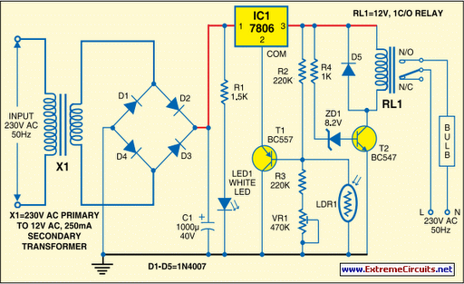
To derive the power supply for the circuit, the 50Hz, 230V AC mains is stepped down by transformer X1 to deliver a secondary output of 12V, 250 mA. The secondary output of the transformer is applied to a bridge rectifier comprising diodes D1 through D4, filtered by capacitor C1 and fed to the input terminal of the regulator (IC1).
The common terminal (pin 2) of IC1 is connected to the ground line of the circuit through transistor BC557 (T1). The transistor is biased by R2, R3, VR1 and LDR1. The grounding of IC1 is controlled by transistor T1, while light is sensed by LDR1. Using preset VR1, you can adjust the light-sensing level of transistor T1. The output of IC1 is fed to the base of transistor T2 (through resistor R4 and zener diode ZD1) and relay RL1.
LED1 connected across the positive and ground supply lines acts as a power-on` indicator. Normally, the resistance of LDR1 is low during daytime and high during nighttime. During daytime, when light falls on LDR1, pnp transistor T1 conducts. The common terminal of IC1 connects to the ground and IC1 outputs 6V. As a result, transistor T2 does not conduct and the relay remains de-energised. The light bulb remains off` as the mains connection is not completed through the relay contacts. During nighttime, when no light falls on LDR1, it offers a high resistance at the base junction of transistor T1. So the bias is greatly reduced and T1 doesn`t conduct. Effectively, this removes the common terminal of IC1 from ground and it directs the full input DC to the output.
Transistor T2 conducts and the relay energises to light up the bulb as mains connection completes through the relay contacts. As LDR1 is in parallel to VR1+R3 combination, it effectively applies only half of the total resistance of the network formed by R3, VR1 and LDR1 to the junction at T1 in total darkness.
In bright light, it greatly reduces the total effective resistance at the junction. The circui t is simple and can be assembled on a small general-purpose PCB. Use a heat-sink for IC1. Make sure that LDR1 and the light bulb are well separated. The circuit can be used for streetlights, tubelights or any other home electrical lighting system that needs to be automated. 🔗 External reference
Related Circuits
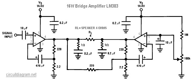
The following diagram illustrates a 16W bridge audio amplifier circuit. The design incorporates two LM383 power ICs in a head connection, making this amplifier a head amplifier. The LM383 is an older model that has been discontinued, which may...
The add-on circuit presented here is useful for stereo systems. This circuit has provision for connecting stereo outputs from four different sources/channels as inputs and only one of them is selected/connected to the output at any one time. When...
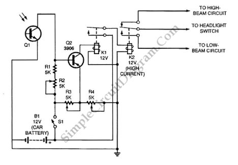
Automatic headlight dimmer circuit diagram for your car's headlight. It ensures safety by providing maximum brightness for the farthest visibility while automatically switching. The automatic headlight dimmer circuit is designed to enhance driving safety by adjusting the brightness of vehicle...

Personal safes are innovative locking storage solutions that open with a simple touch of a finger. These devices are designed as secure storage options for medications, jewelry, firearms, documents, and other valuable or potentially hazardous items. They employ fingerprint...

White Light is an interactive sound and light installation that combines elements of sculpture, musical instrument, and social engagement. It invites viewers to participate in a complex display of sound and light by manipulating controls on one of three...
Currently, batteries are becoming increasingly powerful, serving as the sole energy source for portable electronic devices. The rapid evolution of battery technology has prompted manufacturers of electronic equipment to strive for reduced power consumption in their products, enabling them...