
Automatic Night Lamp Circuit PCB
The automatic night lamp circuit is designed to provide illumination in areas such as staircases and porches without the need for manual intervention. The circuit primarily consists of a Light Dependent Resistor (LDR), a Silicon Controlled Rectifier (SCR), and a few passive components, allowing it to operate efficiently with a standard domestic power supply.
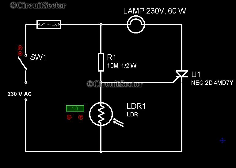
The LDR serves as the primary sensor in this circuit. It is a type of resistor whose resistance decreases with increasing incident light intensity. During the day, when ambient light levels are high, the resistance of the LDR is low, which prevents the SCR from being triggered. As the sun sets and the light levels drop, the resistance of the LDR increases significantly. This change in resistance creates a voltage drop across the LDR, which can be utilized to provide the necessary gate trigger voltage to the SCR.
The SCR acts as a switch that can be turned on with a small gate current. When darkness is detected by the LDR, the voltage across the SCR's gate-cathode terminals reaches a threshold level, allowing current to flow through the SCR and effectively closing the circuit. This action activates the connected lamp, providing the desired illumination.
To adapt the circuit for use with a compact fluorescent lamp (CFL), modifications may be required, such as adjusting the current limiting resistors to accommodate the different electrical characteristics of the CFL compared to a traditional filament lamp.
Overall, this automatic night lamp circuit is a practical solution for enhancing safety and convenience in residential settings, ensuring that essential areas are illuminated during the night without requiring manual operation. The simplicity and cost-effectiveness of the design make it an attractive option for homeowners seeking an automated lighting solution.It is very convenient to light a lamp in our absense in the eving when it gets dark. This automatic night lamp circuit can be used to light staircase light, porch light etc automatically using domestic powersupply. It is very in expensive in construction and we dont have to employ or depend anybody to put on the lights when we are out of station.
We can connect a CFL in place of filament lamp by making necessary alterations to the circuit. An SCR and LDR together plays the role of automation in this circuit. In figure, the resistance of LDR is low during daytime and high during night. So the required trigger pulse is developed across the SCR when it becomes dark and it is applied acrosss the gate cathod terminals and SCR is triggered and the circuit is closed. 🔗 External reference
Related Circuits
Due to the increased level of the transistor amplifier circuit, the control circuit's performance in Figure 16-6 is more sensitive and can accept input control signals superimposed on others (such as voltage, current, and speed feedback signals) to meet...
This circuit is utilized in RS-232 serial interface and current loop circuit applications. It converts voltage signals into a 20mA current signal, with a maximum transmission rate of 1200 bits per second. The CCD IC1 and transistor T1 form...
This schematic represents an FM transmitter capable of delivering an output power of 3 to 3.5 W, operating within a frequency range of 90 to 110 MHz. While the stability of the circuit is acceptable, the integration of a...
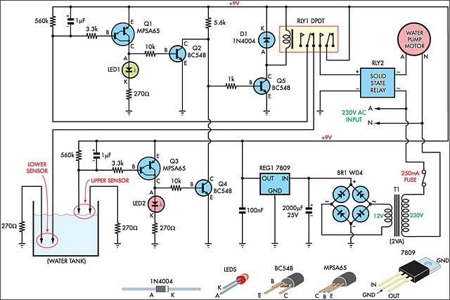
This circuit is designed to effectively fill a header tank for a reticulated water supply on a farm. It supports eight troughs located in various paddocks, where inadequate water supply can have serious repercussions for livestock. Previously, a timer-based...
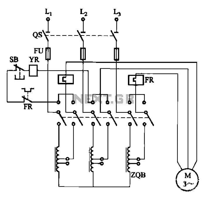
The circuit illustrated in Figure 3-47 involves a three-phase AC motor that is initially connected through a step-down autotransformer. To initiate operation, the power switch is closed, and the operating handle is pushed to the start position. Once the...

A simple circuit that can generate an inverted square wave similar to the one used by the inventor on his function generator. To construct a circuit that produces an inverted square wave, a basic approach involves using a 555 timer...
Warning: include(partials/cookie-banner.php): Failed to open stream: Permission denied in /var/www/html/nextgr/view-circuit.php on line 713
Warning: include(): Failed opening 'partials/cookie-banner.php' for inclusion (include_path='.:/usr/share/php') in /var/www/html/nextgr/view-circuit.php on line 713