
Single-junction transistor trigger circuit 2
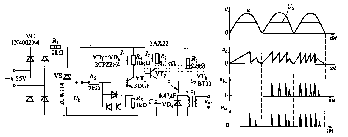
The transistor amplifier circuit, as illustrated in Figure 16-6, showcases a heightened sensitivity that enhances the control circuit's performance. This sensitivity allows the circuit to effectively process multiple input control signals simultaneously. These signals can include voltage levels, current readings, and speed feedback, which are crucial for various applications in electronic systems.
The design of the control circuit incorporates a transistor amplifier that is configured to amplify the desired control signals while filtering out noise and interference. This is achieved through careful selection of transistor characteristics, biasing conditions, and feedback mechanisms. The circuit may utilize operational amplifiers in conjunction with transistors to achieve the desired gain and bandwidth, ensuring that the circuit remains responsive to changes in the input signals.
The ability to superimpose multiple control signals enables the system to operate under various conditions and respond dynamically to feedback. For instance, in a motor control application, the control circuit can simultaneously process speed feedback and current measurements to adjust the voltage supplied to the motor, thereby optimizing performance and efficiency.
Overall, the transistor amplifier circuit serves as a critical component in modern electronic systems, providing the necessary sensitivity and versatility to handle complex control tasks.Due to the increased level of transistor amplifier circuit, the control circuit of Figure 16-6 performance more than plus sensitive, and can input control signal superimposed o n the other (such as voltage, current, speed feedback signal) to meet system requirements.
Related Circuits
An RF probe is a circuit designed for testing equipment that converts high-frequency signals into DC voltage. This conversion facilitates the measurement of RF voltages for testing or adjusting transmitters, receivers, and modulators. The RF probe circuit outlined here...
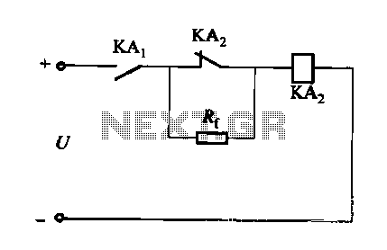
A DC relay or contactor is utilized to enhance the excitation pull-in and release mechanisms in a circuit. The relay circuit, as depicted in Figure 6-28, facilitates improved return line efficiency. When the control relay KAi is activated, its...
A rain sensor alarm circuit is a useful device for alerting when rainfall occurs. The rain detector circuit presented is straightforward, utilizing only three components while maintaining high sensitivity to detect rain or moisture. The sensor can be constructed...
With the help of a simple ceramic piezoelectric detector, it is possible to assemble an interesting and useful impact sensor unit, which can be used to detect... An impact sensor unit utilizing a ceramic piezoelectric detector operates by converting mechanical...
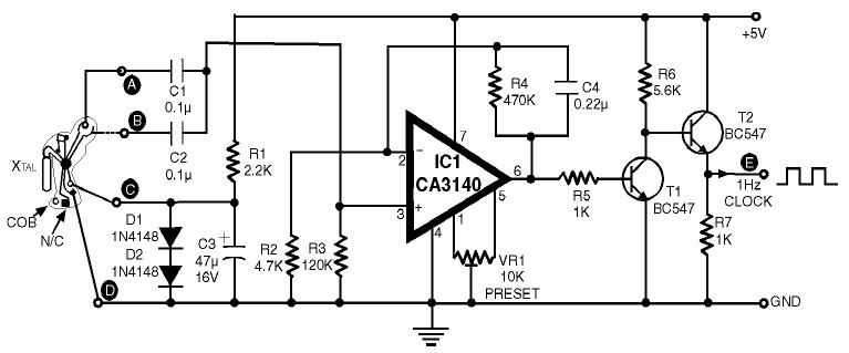
1Hz Clock Generator Circuit with Chip On Board (COB). The COBs used in different watches may differ somewhat in their configuration. However, through trial and error, one can identify the appropriate points corresponding to points A, B, C, and...
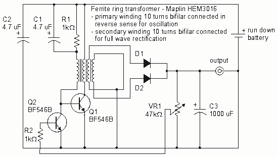
How to create a Joule Thief circuit to power a clock, including circuit details and tips for construction. The Joule Thief circuit is a simple and efficient boost converter that allows the extraction of usable voltage from low-voltage sources, such...
Warning: include(partials/cookie-banner.php): Failed to open stream: Permission denied in /var/www/html/nextgr/view-circuit.php on line 713
Warning: include(): Failed opening 'partials/cookie-banner.php' for inclusion (include_path='.:/usr/share/php') in /var/www/html/nextgr/view-circuit.php on line 713